
“Though I don’t do many PCBs, I guess every hacker must have a reflow oven. So this is a project I’ve been pursuing on and off for nearly 4 years:
A small, portable, and dirt cheap (less than $25) reflow oven.
After a few tests with a traditional electric oven recovered from the trash, I concluded its thermal inertia was so high it would require massive modifications to achieve anything close to a decent reflow profile, and as I didn’t feel like spending much money on a large oven, I looked for a better way.
And I think I found it. Read on for more…
The “oven”
Although Belgium’s national dish is fries (mistakenly called “French fries” in English), we are best known abroad for our waffles. And coincidentally, my wife had just decided to replace our old waffle toaster because its closing clip was broken, so I wondered if I could transform it into a reflow oven.
Of course large PCBs would not fit, but the relatively small size of that toaster would also make it easy to put it away in my small lab. Plus, it has both top and bottom heating elements, and the small volume limits energy losses.
The toaster in question is a “Croq’Gaufres Express” by Moulinex. It has removable hotplates and is limited to 700 Watt, which is not much but I thought it was worth a try. I quickly put together an Arduino with a MAX6675 and K-type thermocouple to monitor the temperature in different conditions, but it was clear that with the hotplates, its inertia was too high, taking around 5 minutes to reach 150°C while most reflow profiles require around 1 or 2 minutes for that ramp.
I then tried to reduce thermal inertia by removing the hotplates and the results were much better. However, the heating elements were then so close to the PCB that they made it overheat, leaving a burned trace on the PCB just under the element (see picture below). Even if high temperatures are not dangerous for the PCB itself, it meant the components would not be evenly heated, and that’s not good.
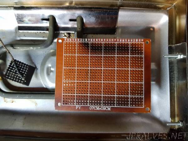
So I needed a way to distribute the heat, and what better heat conductor than a copper plate ? As SMD components are only on the upper side of the PCB, I bought a 0.5mm copper plate and placed it on top, wrapped it around the heating element, and with that set-up, the PCB became evenly heated within a reasonable warm-up time.
I also quickly cut and bent a piece of scrap metal to create a frame and fill the gap left all around the frame by the now removed hotplates, then used some of hard wire as support for the boards and attached the thermocouple to a piece of PCB to simulate a similar thermal inertia,”