
“When Microchip bought Atmel I was afraid that they would discontinue further development of the AVR MCUs and instead only promote their PIC-devices. But it seems this worry was unjustified. New series of ATtinies and ATmegas have been released and these new devices are packed with very useful periferals. At the same time the price of the newer devices are substantially lower than the older ones.
Of particular interest to me is the Event System and the Configurable Custom Logic (CCL) block that makes it possible to route signals between peripherals and pins without having to go through any CPU processing.
This opens up for applications like software configurable switch-mode regulators for voltage translation (step-up/boost, step-down/buck, flyback etc.).
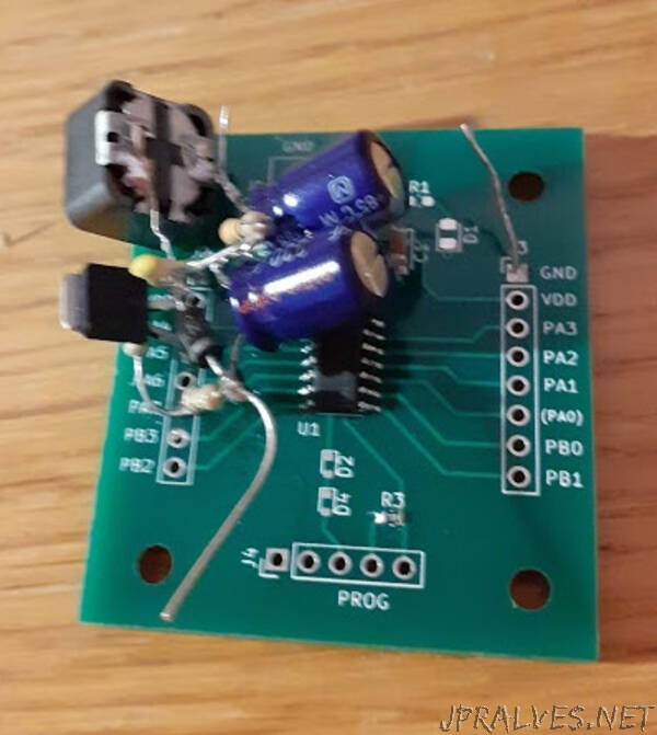
To evaluate this, a boost regulator to deliver +12V from a +5V supply was designed, built and tested.
The blocks drawn are all configured, but then afterwards fully independent, from the CPU. Two timers are utilized. The first, to the upper left, is configured to run continuously and overflows after 30 µs, i.e. at a fixed frequency at around 33 kHz, when set up as in the code below. The overflow signal is logically AND:ed with the state of the analog comparator. This AND gate is implemented by one of the two Look-Up-Tables in the CCL block. The comparator takes its inputs from a pin and the internal DAC. If the voltage detected at the output of the regulator is lower than the DAC set point, the comparator output is high. The signal from the AND gate then starts the second timer in one-shot mode. It is configured such that its comparison output, which is fed to a pin, is high from start to around 15 µs later. If the comparator would be continuously in its high state this all together creates a signal that repeatedly is high 15 µs and low 15 µs (total period time 30 µs).
This signal is intended to drive a transistor to first “charge” an inductor and then give the inductor time to release its energy at a higher voltage.
The voltage at the output is scaled down and compared with the one from the DAC. This ensures regulation to a fixed output voltage. Thanks to the DAC, the regulator output voltage can be tuned digitally without having to change any resistor values.”