
“This project is an I2C to 8-bit Bus converter plus three(3) control bits, primarily designed to handle 2004 and 1602 LCD display modules.
While developing a project, I run into a need for an LCD to display several information. The most common models are the 1602 (16 characters by 2 row) and 2004 (20 characters by 4 rows), which are low cost and easy to source. However, using these models requires 16 wire interface. Running these number of wires from the LCD to the main board is not a good option. Designing the main PCB, and allocating such number of channels are surely a trouble.
I decided to use serial communication, and I choose I2C, as there are already existing I2C to LCD interface board readily available in the market. So I decided to take LCD Models 2004 and 1602 and the existing I2C interface board and started the prototype. However, I found that the I2C interface board is not as I had expected. Sure, I admire its simplicity, where LCD interface fits everything into 8-bit wide bus. It operates the LCD in 4 bit-mode, and the remaining bits are allocated to E, R/W, and R/S pin. That fits perfectly to an 8-bit I2C expander chip, with one remaining bit unused. Most example in the internet is using arduino IDE, with library readily available.
However, despites its simplicity, I still ended up in trouble. I’m a bare metal programmer when it comes to MCU. I’m using Microchip PIC and MPLAB as an IDE. Sorry for Arduino users. I know Arduino IDE is simple and easy to use, but I am stucked to the beauty of using the MCU at the register level with MPLAB as my companion. So the available library is not for me. I have to write my own code. But no worries, your I2C protocol is the same as mine, so as long as you can control any device with I2C bus, then this project can work with yours, regardless what tool you are using.
With the existing I2C interface board in the market, programming the LCD in 4-bit mode requires the single character to be send in multiple bytes over the I2C bus. You have to bit bang the clock, besides spliting the character into two nibbles. It is possible and it works, of course. But while optimizing my code, I found some LCD units not really consistent on their response. But I can get them pretty stable in 8-bit mode, with dedicated control bits. Well, maybe because I don’t have a good control of the timing? I decided not to investigate further, and just take another option. I don’t want to spend extra program memory for that, and I want my main board MCU bandwidth to do other things than babysitting the LCD display.
So, I think it would be better to use an I2C interface board that gives me the joy and happiness that I am looking for. Since I will be possibly using this module for other future projects, I decided to separate it as an independent project, and document it for future reference. And so this project was born as an independent endeavor.
So, what is it?
Basically, this project is an MCU based LCD display interface board that converts I2C bus to 8 bit bus, with extra 3 bits intentionaly allocated to control the E, R/W, and R/S pin of the LCD module. The MCU also controls the backlight through PWM, allowing the user to control the intesity of the LED, or to turn it OFF.
User can send the characters to LCD by simply sending the ascii characters to the I2C bus. There is also a simple protocol implemented to control the LCD. For example, there are special commands to handle the backlight, change the I2C address, or to send command to the LCD, like turning on the cursor. The complete description and operation of the module is described in the attached document below.
The module is small enough to fit at the back of the LCD display. It is designed with PIC18F26K22 chip. I have purposefully exposed ICSP pins, and designed it with dedicated header for programming and debugging. Anybody who knows how to program the PIC can simply reprogram the module for their own joy and happiness.
The components are selected so that it can be easily assembled manually. Resistors and capacitors are all 1206 packages (3216 metric) and the MCU is an SOIC wide body package (7.5x17.9mm 1.27mm pitch). Headers are all 2.54mm. PCB was fabricated by PCBway (www.pcbway.com), and I have shared the project on their site so that anyone can browse through their website and order the pcb.
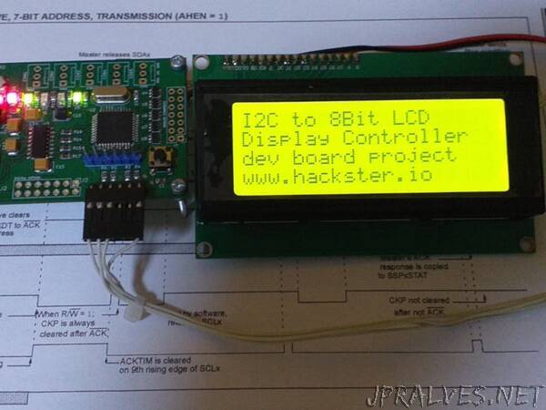
After few Saturdays and Sundays of work, the project came to life!
So for users who want to create the project, steps are below:
Prepare the component list.
If you only need to do a prototype, then you can do it in a breadboad. You have to use through hole components for this. Be critical in your oscillator circuit. Note also that you may need adapter board for the MCU, as it is an SOIC package.
Or, if you want the PCB, you can order it from here. The link will bring you to www.pcbway.com. They fabricated the PCB for this project. (Note that I’m NOT connected to them in anyway. It is so happenned that there is an option for customer to share their PCBs for others. This is a personal project.)
Stick all components together. Connect to your preferred LCD. You can use either 1602 or 2004 (Note that firmware default is 1602, through it works for both, except that if you use 2004 at this time, you can only print into two(2) rows after programming the firmware. You can configure later).
Make sure your hardware is working. Powerup and check currents. Initial power should show low current, maybe below 1mA. That’s okay, the MCU is doing nothing, oscillator may not be working at this time.)
To check your hardware, I would advise create a “Hello World” program. I assume you are acustomed with MPLABX and XC8. You can use the LEDs for blinking LED program to see if it works or not.
Once you are sure your hardware is okay, download the attached source code below. Compile using MPLABX and XC8 Compiler. I’m using MPLABX version 5.40, and XC8 v2.20.
Program the device. You can use PICKIT from Microchip. The ICSP header is compatible with Pickit header. Align Pin1 of PICKIT to Pin1 of the ICSP header. (Early pickit have only 6 pins, Pickit4 have 8).
Try the module. Note that the default I2C address is 0x27. Send any printable character via I2C bus. If you see the charater on the screen, you are good to go.
Download the attached manual below (see “Product Documentation”) as a complete user guide.
Done!”