
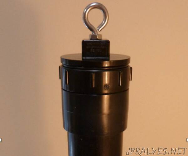
“These instructions describe how to build a low-cost, real-time water level meter for use in dug wells. The water level meter is designed to hang inside a dug well, measure the water level once a day, and send the data by WiFi or cellular connection to a webpage for immediate viewing and downloading. The cost for the parts to build the meter is approximately Can$200 for the WiFi version and Can$300 for the cellular version. The water meter is shown in Figure 1. A full report with building instructions, parts list, tips for constructing and operating the meter, and how to install the meter in a water well is provided in the attached file (Water Level Meter Instructions.pdf). The meters have been used to develop a regional, real-time shallow aquifer monitoring network in Nova Scotia, Canada: https://fletcher.novascotia.ca/DNRViewer/index.htm…
The meter uses an ultrasonic sensor to measure the depth to water in the well. The sensor is attached to an Internet-of-Things (IoT) device that connects to a WiFi or cellular network and sends the water level data to a web service to be graphed. The web service used in this project is ThingSpeak.com, which is free to use for non-commercial small projects (fewer than 8,200 messages/day). In order for the WiFi version of the meter to work, it must be located close to a WiFi network. Domestic water wells often meet this condition because they are located close to a house with WiFi. The meter does not include a data logger, rather it sends the water level data to ThingSpeak where it is stored in the cloud. Therefore, if there is a data transmission problem (e.g. during an Internet outage) the water level data for that day are not transmitted and are permanently lost.
The meter was designed and tested for large diameter (0.9 m inside diameter) dug wells with shallow water depths (less than 10 m below ground surface). However, it could potentially be used for measuring water levels in other situations, such as environmental monitoring wells, drilled wells, and surface water bodies.
The meter design presented here was modified after a meter that was made for measuring water levels in a domestic water tank and reporting the water level via Twitter, published by Tim Ousley in 2015: https://www.instructables.com/id/Wi-Fi-Twitter-Wa…. The main differences between the original design and the design presented here are the ability to operate the meter on AA batteries instead of a wired power adaptor, the ability to view the data in a time-series graph instead of a Twitter message, and the use of an ultrasonic sensor that is specifically designed for measuring water levels.
Step-by-step instructions for constructing the water level meter are provided below. It is recommended that the builder read through all constructions steps before starting the meter construction process. The IoT device used in this project is a Particle Photon, and therefore in the following sections the terms IoT device and Photon are used interchangeably.
Supplies:
Electronic Parts:
- Sensor – MaxBotix MB7389 (5m range)
- IoT device - Particle Photon with headers
- Antenna (internal antenna installed inside the meter case) – 2.4 GHz, 6dBi, IPEX or u.FL connector, 170 mm long
- Battery pack – 4 X AA
- Wire – jumper wire with push on connectors (300 mm length)
- Batteries – 4 X AA
Plumbing and Hardware Parts:
- Pipe - ABS, 50 mm (2 inch) diameter, 125 mm long
- Top cap, ABS, 50 mm (2 inch), threaded with gasket to make a watertight seal
- Bottom cap, PVC, 50 mm (2 inch) with ¾ inch female NPT thread to fit sensor
- 2 Pipe couplers, ABS, 50 mm (2 inch) to connect top and bottom cap to ABS pipe
- Eye bolt and 2 nuts, stainless steel (1/4 inch) to make hanger on the top cap
- Other materials: electrical tape, Teflon tape, solder, silicone, glue for assembling case”