
“This project started as a simple experiment. During my research over the ATMEGA328P’s datasheet for another project, I found something rather interesting. The Timer1 Input Capture Unit. It allows our Arduino UNO’s microcontroller to detect a signal edge, store a timestamp, and trigger an interrupt, all in hardware.
I then wondered in which application it could be useful, and how to test it. As I want to get a logic analyzer for some time now, I decided to try implementing one in my Arduino UNO board, just to test the feature, and see if we can get good results out of it.
I am not the only one that had this idea, and you will find plenty of them by just googling “Arduino Logic Analyzer”. At the beginning of the project, as it just started as an experiment, I wasn’t even aware that people already made it, and was impressed by the good results they achieved with this little piece of hardware. However, I couldn’t find another project using the input capture unit, so if you have already seen this, let me know!
To summarize, my logic analyzer will:
Have one channel,
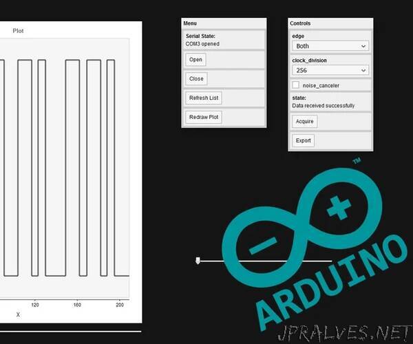
Have a graphical interface,
Communicate with the interface through USB,
Run on an Arduino UNO board.
It will finally have a 800 samples memory depth, and was able to successfully capture a 115200 bauds UART message (I didn’t really tested it at higher speeds).
This instructable contains both the “how it works” and “how to use it” parts of this project, so for those that are not interested by the technical side, you can directly jump to the step 4.
Supplies:
I wanted to keep the analyzer as simple as possible, so requiring very little hardware.
You will need:
An Arduino UNO board (or equivalent as long as it relies on the ATMEGA328P MCU),
A computer,
Something to debug (an other Arduino UNO board works fine to do some testings).
The code for both the Arduino UNO and web interface can be found here.
You will also need the p5.serialcontrol, and PulseView software.”