
“If you are planning to install an off-grid solar system with a battery bank, youll need a Solar Charge Controller. It is a device that is placed between the Solar Panel and the Battery Bank to control the amount of electric energy produced by Solar panels going into the batteries. The main function is to make sure that the battery is properly charged and protected from overcharging. As the input voltage from the solar panel rises, the charge controller regulates the charge to the batteries preventing any overcharging and disconnect the load when the battery is discharged.
You can go through my Solar projects on my website: www.opengreenenergy.com and YouTube Channel: Open Green Energy
I am making a YouTube video for this project. Keep in touch for further updates.
Types of solar charge controllers
There are currently two types of charge controllers commonly used in PV power systems :
1. Pulse Width Modulation (PWM) controller
2. Maximum Power Point Tracking (MPPT) controller
In this Instructable, I will explain to you about the PWM Solar Charge Controller. I have posted few articles on PWM charge controllers earlier too. The earlier version of my solar charge controllers are quite popular on the internet and useful for people all around the globe.
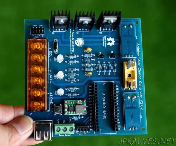
By considering the comments and questions from my earlier versions, I have modified my existing V2.0 PWM Charge Controller to make the new version 2.02.
The following are the changes in V2.02 w.r.t V2.0:
1. The low efficient linear voltage regulator is replaced by buck converter MP2307 for 5V power supply.
2. One additional current sensor to monitor current coming from the solar panel.
3. MOSFET-IRF9540 is replaced by IRF4905 for better performance.
4. Onboard LM35 temp-sensor is replaced by a DS18B20 probe for accurate battery temperature monitoring.
5. USB port for charging smart devices.
6. Use of single fuse instead of two
7. One additional LED to indicate Solar Power Status.
8.Implementation of 3 stages charging algorithm.
9. Made a custom PCB for the project
Specification
1.Charge controller as well as energy meter
2. Automatic Battery Voltage Selection (6V/12V)
3.PWM charging algorithm with auto charge setpoint according to the battery voltage
4.LED indication for the state of charge and load status
5. 20x4 character LCD display for displaying voltages, current, power, energy, and temperature.
6.Lightning protection
7.Reverse current flow protection
8.Short Circuit and Overload protection
9. Temperature Compensation for Charging
10. USB port for Charging Gadgets
Supplies:1. Arduino Nano
2.P-MOSFET - IRF4905
3.Power diode -MBR2045
4.Buck Converter-MP2307
5.Temperature Sensor - DS18B20
6.Current Sensor - ACS712
7.TVS diode- P6KE36CA
8.Transistors - 2N3904
9.Resistors ( 100k x 2, 20k x 2,10k x 2,1k x 2, 330ohm x 7)
10.Ceramic Capacitors (0.1uF x 2)
11. 20x4 I2C LCD
12.RGB LED
13.Bi-Color LED
15.Jumper Wires/Wires
16.Header Pins
17.Heat Sinks
18.Fuse Holder and fuses
19.Push Button
22.Screw terminals 1x6 pin
23.PCB Standoffs
24. USB Socket
Tools :
1.Soldering Iron
2. Desoldering Pump
2.Wire Cutter and Stripper
3.Screw Driver”