
“I have read an article on the teardown of a dashboard mileage manipulator dongle on Hackaday. A “CAN bus filter” device was found in a vehicle, connected to the back of its instrument cluster. When it was removed and the original connections were restored, the odometer immediately showed 40 000 kilometers more than before. The author made a quick teardown and analysis on the device but because it was supposed to be locked (according to the article), the firmware was not extracted, leaving the big question unanswered:
What it does and how it does it?
Mileage manipulation is illegal in many countries and one could easily go to jail if kept doing it. Still, this is quite common practice on the used car market and mileage manipulator devices could be easily purchased by anyone. The main purpose of these “greyish” tools is to mislead and to fool the buyers. Considering this, I was happy to extend my “to be hacked” list with them, and I also wanted to see how they work and if there is anything to do against the “attack”. Everything was set for a cool project combining car hacking, hardware hacking and reverse engineering. Due to the nature of the topic, I expect readers with less relevant technical knowledge as well, so I tried to provide a bit more details and explanation, to make sure everyone can follow along.
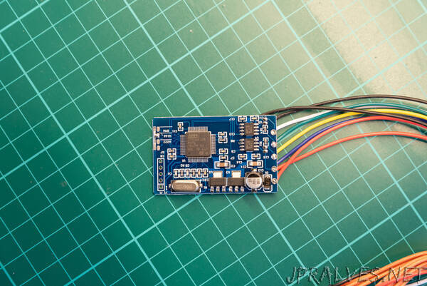
These boards can be found on eBay for $15-25, e.g. by searching for “18 in 1 Universal CAN Filter“. Several sellers are providing them under different fantasy names and with some variance in their supported vehicle list. I decided to order two type of CAN filters from two different sellers. They had the same functionalities, but their PCB looked a bit different. Both CAN filter devices support a bunch of car models from two major German OEMs (just look for the description in the eBay product pages). After one makes the mileage manipulation, this device will prevent the odometer’s sync and increase, by manipulating the relevant communication. For easier reference, I am calling them as #blue CAN filter and #green CAN filter in the following sections.
The devices are designed to be connected to the CAN bus in a MITM (Man In The Middle) setup, by intercepting the CAN communication between the instrument cluster and the rest of the car. The circuits are quite simple. By identifying the main components and following the PCB traces I reversed the schematics. At the first look there are some trivial differences in the HW design and in the components used, but the main structure is identical. Both boards use the STM32F105 (STM32F105RBT6 to be precise) general purpose microcontroller. Its notable features are: 32 bit ARM Coretex-M3 core, 128k flash, 64k SRAM, Serial Wire Debug (SWD) and JTAG interfaces, 2x CAN interfaces. There are solder jumper pads connected to the MCU’s GPIOs (PC10, PC11, PC12 and PA15) for device configuration, 2 CAN transceivers to drive the physical CAN bus, and 2 LDOs providing regulated 3.3V for the MCU and 5V for the CAN transceivers. Config selector solder jumpers, when shorted, are actually pulling the given GPIOs to ground. As there is no additional resistor connected to these pins, the GPIOs should be configured to input, with internal pull-ups. This means that their default read value is logic high until the solder jumper config does not pull them down to ground. The only meaningful difference between the two boards is that the #green CAN filter device exposes serial programming connections (PA9/USART1_TX, PA10/USART1_RX together with BOOT0 boot mode selector), while the #blue CAN filter board exposes the SWD debug interface (PA13/SWDIO, PA14/SWCLK and BOOT0 pins) on the unpopulated pin headers. Note that the #green CAN filter also exposes the SWD connections, but on small test points only.
Obvious next step is to connect to the debug and programming interfaces to try to download the firmware. Normally, this should not be possible, because with basically zero effort the debug access could be easily disabled, and firmware readout could be also prevented. Important to mention that we are talking about a general purpose microcontroller, which is not supposed to be resilient against advanced HW hacking attacks, that can be used to bypass the applied protections. Nevertheless, using the device provided security features is the bare minimum to raise the bar for the attackers.
With unrestricted access to low level debug interfaces, such as JTAG or SWD, one could take full control over the device, such as stopping and altering the code execution, accessing memory and registers, or even dumping the firmware. There are circumstances, where debug access is possible, but its features and memory access are limited. For example, flash dumping is not possible, so this should be always tested according to the given device’s security features.
For this test, I flashed the Black Magic Probe firmware (JTAG/SWD debugging tool, with built-in GDB server) to my custom HW hacking interface and connected it to the exposed SWD connections (PA13/SWDIO, PA14/SWCLK) on the #blue CAN filter. After powering on the environment just couple of steps were needed:
With ‘arm-none-eabi-gdb’ (architecture specific GNU debugger) I connected to the Black Magic Probe remote GDB server
With ‘swdp_scan’ available device was checked on the SWD interface
After attaching to the identified target device, access to registers and memory were checked
Then a simple ‘dump memory binary’ command targeting 0x08000000 address (where the flash memory is mapped, see memory mapping from datasheet) was executed
Voila, the firmware was dumped. Surprisingly, the “vendor” did not make any effort to lock down the MCU. Access was not restricted neither to the debug interface nor to the flash memory. I was surprised and to be honest, disappointed a bit.”