
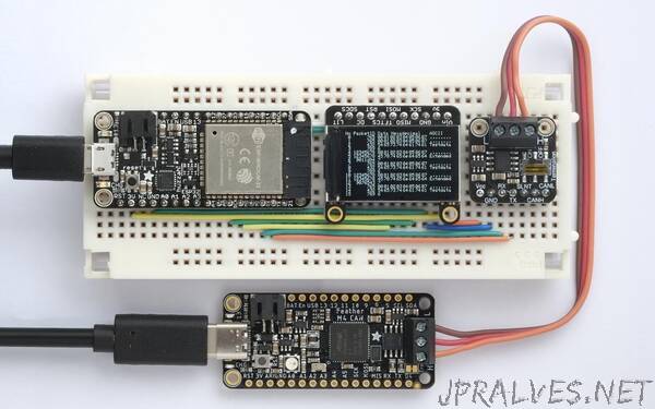
“This is a simple CAN Bus monitor that displays information about the packets on a CAN Bus
It’s based on an Adafruit ESP32 Feather, a CAN Bus Transceiver, and a 240x135 TFT Display.
I tested it by sending packets from an Adafruit Feather M4 CAN Express board, based on an ATSAME51.
Introduction
CAN (Controller Area Network) Bus is a communications interface widely used in the automotive industry. It was developed by Bosch and is now ISO approved. Like I2C it uses two wires and ground, but it uses differential signals enabling it to communicate reliably at a faster data rate over longer distances, typically up to 1000 meters with suitable cabling.
Although CAN Bus was originally developed for use in vehicle electronics, it’s also ideal for use in wider applications such as home automation, model railways, and plant irrigation. I’ve recently been experimenting with it, and designed this monitor to help me debug the packets being sent over the bus.
CAN Bus cabling
The CAN bus consists of two signal lines: CAN High (CAN-H) and CAN Low (CAN-L), with an additional common GND line. Each end of the bus should be terminated with 120Ω resistors to reduce signal reflections, and most transceivers include switched termination for this purpose. The cabling is typically a twisted pair for CAN-H and CAN-L, plus a third GND cable. Shielding is optional, but if provided, only one end should be connected to GND. The speed of the bus can be 1 Mbps for lengths of up to 40 metres, or up to 1000 metres at the lower speed of 50 kbps.
CAN Bus support
Support for CAN Bus is being included in an increasing number of microcontrollers and microcontroller boards, such as the ESP32 family, and the recently released Arduino Uno R4 Minima and WiFi boards. Note that although these boards include support for the CAN Bus protocol, they need the addition of an external transceiver to connect to the CAN Bus line. Adafruit have also released the Feather M4 CAN board which is based on the ATSAME51, and it includes a transceiver on the board.
The differential signal used by CAN Bus requires a voltage swing of 5V, so if you are using the transceiver with a 3.3V microcontroller you will need to provide an additional 5V supply. This isn’t usually a problem on boards powered by USB, because they provide a 5V power output. Alternative you could use a voltage doubler to generate the 5V from 3.3V.
A popular transceiver is the TJA1051 [1], available on a breakout board from Adafruit [2].; this board includes a charge-pump voltage doubler to generate the 5V supply from a 3.3V supply.
If you want to provide CAN Bus to a board that doesn’t already support it you can use an interface chip such as the MCP2515 or MCP25625, which convert between SPI and CAN Bus. One such board is the Arduino MKR CAN Shield [3]. With the MCP2515 you need to add a separate transceiver, but the MCP25625 includes a built-in transceiver.”