
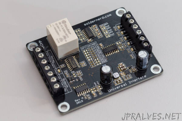
“It’s time to present a relatively simple yet useful device: the Universal Interface. The need for this little helper arised when building the control for my CNC milling machine. But that’s a major project that I will introduce another time. Today it’s only about this little board.
My challenge was that I had to connect to and from a variety of external devices. Such as coolant pumps, pneumatic valves, probes and the like. Input and output signals could be anything from 5V logic, open collector logic, 24V logic to a relay. And they could be active low or active high.
Some situations also required a bit of logic. Not much but still some. Something like an AND and an OR gate or so. None of those circuits were challenging to design. But there were several of those and I didn’t really want to custom design and build a board for each one. Besides the fact that some in- and outputs were not entirely final yet or could change in the future. In other words, I wanted a single design that is flexible enough to handle all the present and future little challanges.
Now to the design. There are 3 inputs (A, B and C) plus an enable input (EN). Each of these inputs is 24V tolerant and can be equipped with pull-up or pull-down resistors. And each of them can be configured to be either active high or active low. And of course, each of these inputs is nicely debounced by running it trough an RC filter followed by a Schmitt triggered logic gate. The logic state of each input is indicated with an orange LED located next to the input.
Next comes the logic part. It uses a 74HC151 8-input logic multiplexer. The three inputs A, B and C select, which of 8 possible inputs is selected. The logic value of these inputs is then determined by 8 resistors as shown below. This allows an arbitrary logic function to be implemented in hardware. Nothing on this board requires software, it’s all hardware.
Then comes the output stage. There is only one single logic output but it is provided in multiple varieties:
First, there is a single-pole, double-throw (SPDT) relay that is good up to 250 volts and 10 amps.
Then there is a powerful open collector output that can drain up to 2 amps. Flyback diodes are already included so this output can directly be used to drive another relay, a motor or whatever.
Then there is a standard CMOS 5V logic output. It can source or drain up to something like 25mA, pretty standard really.
And then there is also a 24V logic output which can optionally be equipped with a pulldown resistor or as a push-pull output as you know it from a typical CMOS gate. It can easily sink or source something like 500mA, maybe more. Protection diodes are also provided.”