
Introduction
Hi there,
I was challenged by Seeed Studio to make a review of a Raspberry PI Zero W.
So here are my thoughts.
I’ll show you how to setup the Micro-SD Card to use to Raspberry PI Zero W to connect to your wireless network headless. Besides the Raspberry PI Zero W board, you need a micro SD Card with at least 8GB and an power supply with an USB micro cable.
About Seeed Studio
Seeed is the IoT hardware enabler providing services over 10 years that empower makers to realize their projects and products. Seeed offers a wide array of hardware platforms and sensor modules ready to be integrated with existing IoT platforms and one-stop PCB manufacturing and Prototype PCB Assembly. Seeed Studio provides a wide selection of electronic parts including Arduino, Raspberry Pi and many different development board platforms. Especially the Grove System help engineers and makers to avoid jumper wires problems. Seeed Studio has developed more than 280 Grove modules covering a wide range of applications that can fulfill a variety of needs.
Footprint and features
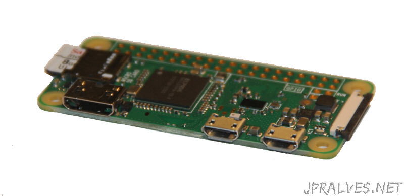
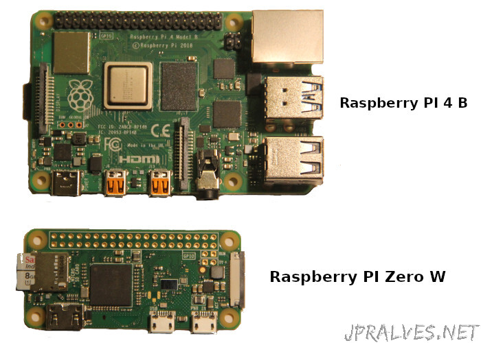
The Raspberry PI Zero series is a smaller version of the Raspberry PI A/B A and has fewer external outputs and less computing power. But the main difference is it’s size and cost which makes it perfect for small projects.
Sharing the same Pinout has its big brother, it allows to interface with different devices using the same recipes as the ones for the Raspberry PI.
Although smaller it still allows you to connect an HDMI output device like a TV or a monitor, a CSI Camera and an external USB hub for connecting other USB devices like a keyboard, a mouse, a webcam or a pen drive. It lacks support of a wired Ethernet connection.
This version of Raspberry PI Zero W has Wireless and Bluetooth interface.
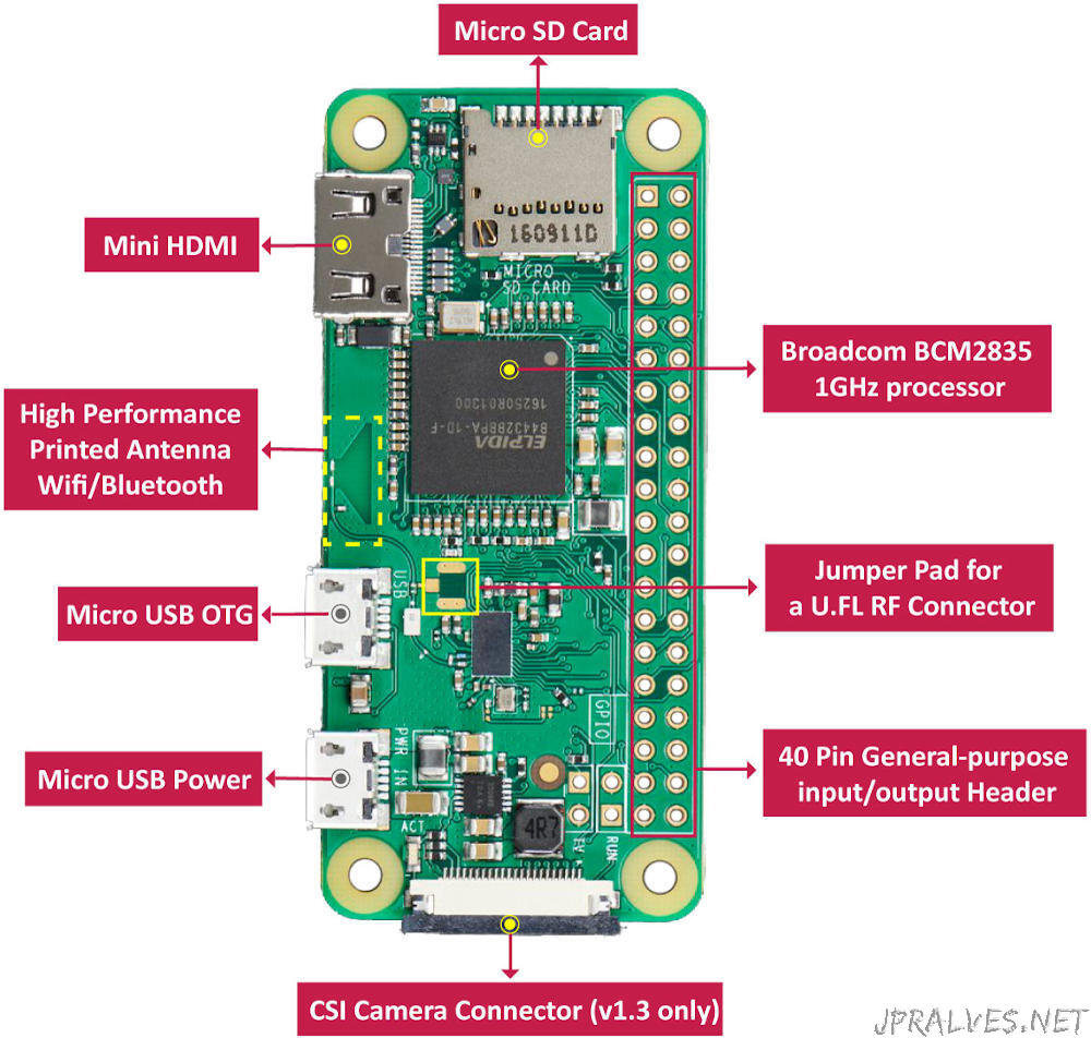
Main Features
- 1Ghz, single-core CPU
- 512MB RAM
- Mini HDMI port
- USB OTG port
- Power via micro USB
- 40-pin GPIO connection
- Composite video pins
- CSI camera connection
- 802.11 b/g/n wireless LAN
- Bluetooth 4.1 / BLE
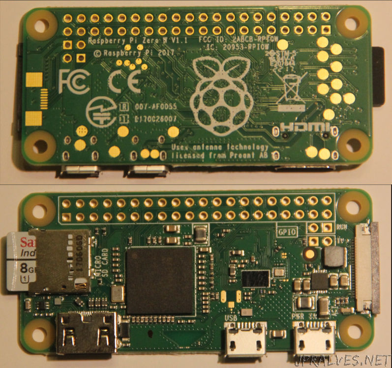
Dimensions:
- 66.0mm x 30.5mm x 5.0mm
It weights about 10g.
Setting Up
The Raspberry PI Zero W uses a Micro SD card. To set it up, you must download the proper image for it. I’ll be using official Raspbian image to do it.
Navigate to the raspberrypi.org downloads page and download the correct image. For this setup, we’ll use the “Raspbian Buster Lite” edition.
At the time of writing, the version available is the “September 2019”. Later versions might behave differently so this instructions might need to be adjusted.
After downloading the image, either with the torrent file or the direct download you should have a zip file.
To ensure that the correct image is downloaded and it is in perfect conditions you can check for its SHA256 hash value (instructions for Linux):
$ sha256sum 2019-09-26-raspbian-buster-lite.zip
a50237c2f718bd8d806b96df5b9d2174ce8b789eda1f03434ed2213bbca6c6ff  2019-09-26-raspbian-buster-lite.zip
If the value matches the one in the site, then it is correct.
Next step is to unzip the file. In Linux you can use the unzip command.
$ unzip 2019-09-26-raspbian-buster-lite.zip
Archive:  2019-09-26-raspbian-buster-lite.zip
  inflating: 2019-09-26-raspbian-buster-lite.img
Once the file is inflated we need to write it to the micro SD Card.
The file must be written in a special way and not copied directly to the SD card.
Writing image file to micro SD Card
Insert an SD card that is 8GB or greater in size into your computer.
Note: using the dd tool can overwrite any partition of your machine. If you specify the wrong device in the instructions below, you could delete your primary Linux partition. Please be careful. If you have doubts on how to use this tool please use balenaEtcher instead.
To accomplish this task I’m going to use native tools found on Linux. For other OS you should use the recommended tool by raspberrypi.org - balenaEtcher.
Insert the micro SD Card into the computer and execute the following command:
$ lsblk -p
NAME             MAJ:MIN RM   SIZE RO TYPE MOUNTPOINT
/dev/sda           8:0    0 465,8G  0 disk
├─/dev/sda1        8:1    0   436G  0 part /home
└─/dev/sda2        8:2    0  29,8G  0 part [SWAP]
/dev/mmcblk0     179:0    0   7,4G  0 disk
└─/dev/mmcblk0p1 179:1    0   7,4G  0 part /run/media/jpralves/6531-6333
/dev/nvme0n1     259:0    0 232,9G  0 disk
├─/dev/nvme0n1p1 259:1    0   512M  0 part /boot/efi
└─/dev/nvme0n1p2 259:2    0 232,4G  0 part /
Locate the device that is mapped as the SD Card (in our case /dev/mmcblk0) it might be listed as something like /dev/mmcblk0 or /dev/sdX (with partition names /dev/mmcblk0p1 or /dev/sdX1 respectively), where X is a lower-case letter indicating the device (eg. /dev/sdb1). The right column shows where the partitions have been mounted (if they haven’t been, it will be blank).
If any partitions on the SD card have been mounted, unmount them all with the umount command, for example umount /dev/mmcblk0p1.
After that, execute the dd command to copy write the image file to the SD Card:
$ dd if=2019-09-26-raspbian-buster-lite.img of=/dev/mmcblk0 bs=1M conv=fsync oflag=direct status=progress
If you get the error dd: failed to open '/dev/mmcblk0': Permission denied execute the same command with the sudo prefix like this:
$ sudo dd if=2019-09-26-raspbian-buster-lite.img of=/dev/mmcblk0 bs=1M conv=fsync oflag=direct status=progress
2236612608 bytes (2,2 GB, 2,1 GiB) copied, 165 s, 13,6 MB/s
2144+0 records in
2144+0 records out
2248146944 bytes (2,2 GB, 2,1 GiB) copied, 165,852 s, 13,6 MB/s
After the write is over there should be two partitions in the sd-card:
$ sudo fdisk -l /dev/mmcblk0
Device         Boot  Start     End Sectors  Size Id Type
/dev/mmcblk0p1        8192  532479  524288  256M  c W95 FAT32 (LBA)
/dev/mmcblk0p2      532480 4390911 3858432  1,9G 83 Linux
The first partition contains the bootstrap part of the process and the second partition contains the root file system of the Linux file-system.
For more information regarding writing the image in the SD Card see page Installing operating system images.
Configure wireless and ssh connection
To configure a wireless access at boot create a file named wpa_supplicant.conf in the first partition with the following content:
ctrl_interface=DIR=/var/run/wpa_supplicant GROUP=netdev
update_config=1
network={
    ssid="THE_SSID"
    psk="WIFI_PASSWORD"
    key_mgmt=WPA-PSK
}
Replace THE_SSID with your Wifi SSID and the WIFI_PASSWORD with the password.
This file will configure the Wifi in WPA2 mode.
Note: There are other modes to configure the Wifi in Raspbian but are insecure and should be avoided.
Configure ssh connection
To enable ssh at first-boot create a file named ssh in the first partition.
$ touch ssh
First connection to the Raspberry PI Zero W
Put the micro SD card in the Raspberry PI Zero and power it up. After a few seconds the blinking green led besides the power connection should stabilize. At that time the Raspberry PI Zero has completed the boot.
Use a terminal to connect to it over ssh:
$ ssh pi@raspberrypi.local
The default user is pi and the default password is raspberry. Change the password as soon as possible to a unique one.
You can change the user password with the passwd command.
Configuring the Raspbian
Use the command sudo raspi-config to make the initial configuration of your Raspberry PI Zero W
Additional Setup:
- 1 Change User Password -> Setup a new password if not done before.
- 2 Network Options -> N1 Hostname -> rpizerow
- 3 Boot Options -> B1 Desktop / CLI -> B1 Console
- 4 Localisation Options -> I1 Change Locale -> Select additionally “en_US.UTF-8 UTF-8” -> en_US.UTF-8
- 4 Localisation Options -> I2 Change Timezone -> select Geographic area and city or region
- 5 Interfacing Options -> P2 SSH -> Yes
- 7 Advanced Options -> A1 Expand Filesystem
- 7 Advanced Options -> A3 Memory Split -> 16
- 8 Update
Quit -> Reboot
After rebooting, connect again using ssh (with the new name - ssh pi@rpizerow.local) command and issue the following commands:
$ sudo apt update
$ sudo apt upgrade -y
$ sudo reboot
This will update all the packages on the Raspbian Linux installed.
Making something useful
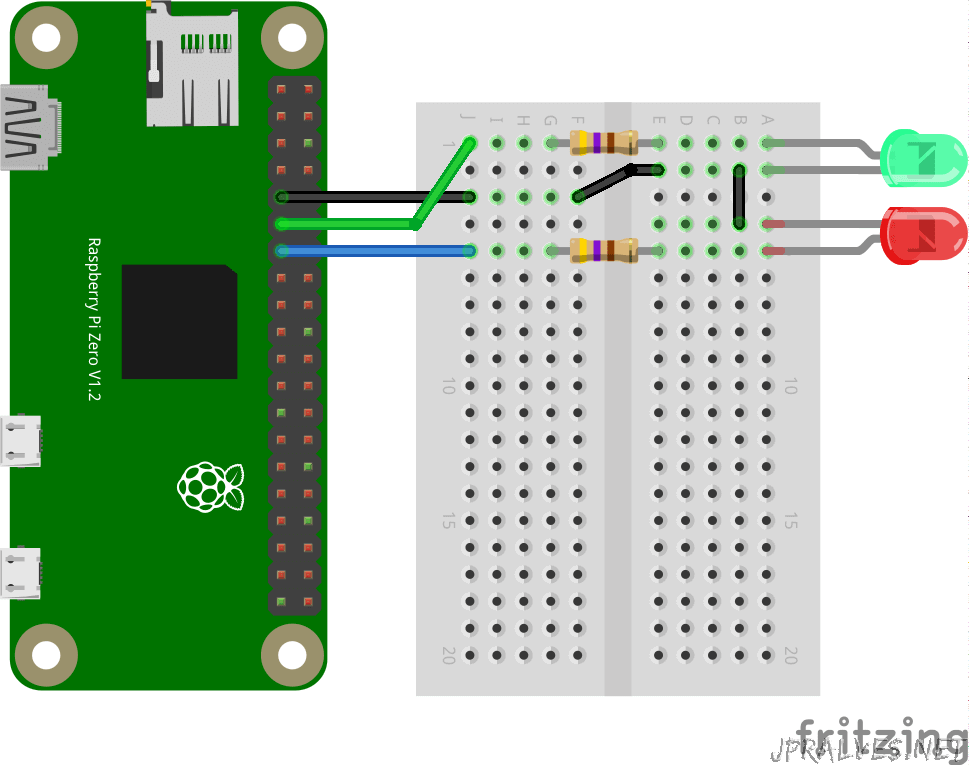
This simple project shows how to enable a simple webserver to control two LEDs attached to ports of the Raspberry PI Zero W.
This project uses Python 3 with Flask as the webserver and uses the rpi.gpio library to control LEDs.
Install flask and rpi.gpio modules:
$ sudo apt install python3-flask python3-rpi.gpio -y
Create a file named my-webserver.py:
#!/usr/bin/python3
# -*- coding: utf-8 -*-

import RPi.GPIO as GPIO
import time
from flask import Flask, escape, request, render_template

pins = {"green": 17, "red": 27}
pins_state = {"green": 0, "red": 0}

app = Flask(__name__, template_folder='.')
GPIO.setmode(GPIO.BCM)
GPIO.setwarnings(False)
for led_color in pins:
    GPIO.setup(pins[led_color], GPIO.OUT)
    GPIO.output(pins[led_color], pins_state[led_color])


@app.route('/')
def root():
    for led_color in pins:
        state = 1 if escape(request.args.get(led_color, "off")) == 'on' else 0
        pins_state[led_color] = state
        GPIO.output(pins[led_color], pins_state[led_color])

    return render_template('main.html', pins_state=pins_state)


def main():
    try:
        app.run(debug=False, host='0.0.0.0', port=5000)

    except KeyboardInterrupt:
        # If CTRL+C is pressed, exit cleanly:
        print("CTRL+C is pressed")
    finally:
        GPIO.cleanup()


if __name__ == '__main__':
    main()
Create another file called main.html:
<!DOCTYPE html>
<html lang="en">
  <head>
    <meta charset="utf-8">
    <title>My Website</title>
    <meta name="viewport" content="width=device-width, initial-scale=1.0">
  </head>
  <body>
    <h1>My Website</h1>
    <p>In this site you can switch the state of two leds</p>

    <form id="leds" action="/" method="get" onChange='submit();'>
{%- for led_color in pins_state %}
    <p>
      <input type='checkbox' id="{{led_color}}" name="{{led_color}}" value="on" {{ 'checked' if pins_state[led_color]==1 }}>
      <label for="{{led_color}}">{{led_color|upper}}</label>
    </p>
{%- endfor %}
    </form>
  </body>
</html>
You can use a command called nano to edit the files in the Raspberry PI Zero W or you can edit them locally and then execute the following command to copy the file to the PI:
$ scp my-webserver.py pi@rpizerow.local:
$ scp main.html pi@rpizerow.local:
The source of this project can be downloaded from github in jpralves/rpi-webserver
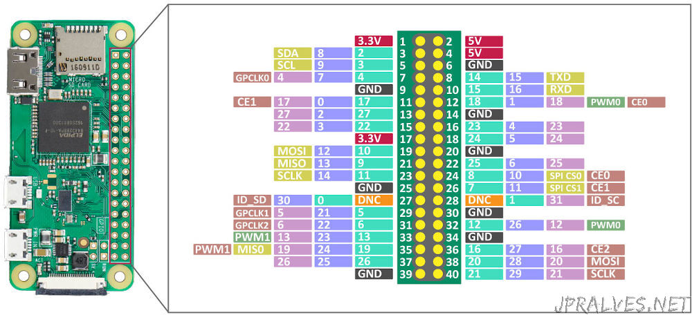
The script has been configured to use the following GPIO:
- Green LED - Pin 11 - GPIO 17
- Red LED - Pin 13 - GPIO 27
- GND - Pin 9
Run the app with the following command:
$ python3 ~/my-webserver.py
 * Serving Flask app "my-webserver" (lazy loading)
 * Environment: production
   WARNING: Do not use the development server in a production environment.
   Use a production WSGI server instead.
 * Debug mode: off
 * Running on http://0.0.0.0:5000/ (Press CTRL+C to quit)
Now use a browser in your PC and navigate to webserver
Unfortunately it does not work in android. To access from android you should use the IP Address and not the name.
To get the IP Address of your Raspberry PI Zero W use the following command:
$ hostname -I
192.168.1.166
In my case, the returning IP Address is 192.168.1.166 - a private IP. Your’s might be different. To access the webserver go to http://THE_IP_ADDRESS:5000/.
Useful links
Special thanks
Last, but not least, I would like to thank seeed studio for providing me the chance to test the Raspberry PI Zero W and making this useful article available to everyone.