
“In this tutorial I will describe how to create a secure and reliable wireless plug based on the tiny ESP8266 D1 Wemos mini for controlling appliances in your home.
Cheap 433MHz Remote Controlled Switches have their advantage of being cheap and easy to use, you buy them push 1-2-3-4 ON/OFF on the remote and they just work out-of-the-box but from security point of view they are terrible, only that does not control them who don’t want to. Someone can walk up to your home with 4-5 different set of remotes and with a good chance he is now in control of at least some of your wireless plugs. This by itself would not even be an issue if they would not be unreliable. 95% of the time they work but what about the 5% when they don’t. That is unacceptable for engineers. Most of these remotes implement repeated resending to increase the success rate (when you push the button on a remote once it sends the ON packet multiple times and hopes for the best). You might want to control some more important components than lights like solenoids or motors with these and since they don’t contain a transmitter, don’t signal back. There is no way for you to know if the device you sent the command to, turned ON or OFF.
I started to design this plug with barebone Atmega326P due to it’s low power consumption and it was just enough for the purpose but when trying to implement wireless encryption with such a tiny MCU I ran into difficulties so it remained a PoC. I will still include my research in a chapter, it might be useful for someone in the future. As a side note here at the start that playing with the mains voltage (110V/230V) is dangerous, if you have just started with electronics you should only build low voltage circuits, this build is only for experienced engineers (build it for your own risk).
After not having enough different Home Easy, Intertechno switches in my home I have bought a bunch of secondhand Home Easies again (due to they had a working Arduino Library already) but then I sadly noticed that this series using different encoding or preamble, the Intertechnos (with mechanical rotary selectors) regularly misaligned when they were re-plugged and all of them can be considered unreliable due to the way they work so it was finally time to design my own wireless plug and stop using these commercial :smart: plugs once and for all.
These wireless plugs are very simple devices, they powering their main circuits with a cheap inefficient transformerless power supply (TPS) circuit which steps the mains (230/110V) down to lower voltages (then regulates it AC->DC) what the circuit needs. Then there is a 433Mhz RX module (which looks familiar (same?) to what we can buy for the Arduino’s) which goes into the main MCU which processes the data (some more advanced devices can be put into learning mode) and if the incoming signal matches with the ON/OFF signal then they turn the relay ON/OFF.
There are plenty of good tutorials on Instructables about how do they work and how to use them with the Arduino such as: https://www.instructables.com/id/Using-433MHz-Remote-Controlled-Switches-on-Arduino/
I used different models of HE (Home Easy), Intertechno, noname switches in the past what I can sort into 5 categories:
1, Single signal ON/OFF switch with RCswitch library. These devices are the worst, they don’t have a specific ON or OFF signal they will go into ON position the first time they are connected to the main then they basically flip flopping, you cannot determine the state. They are not good for anything, avoid them.
2, Wireless ONLY smart plugs with dials/dip switches, they can be only turned ON/OFF with the remote there are 2 dials to adjust the GROUPS/SWITCHES like Group III Switch C. The problem with these dials that even from small fractions (pulling the plug out and replugging it) they can shift out of position, also since there is no manual ON/OFF button on the device if your remote control fails or you just want to switch the thing on right now you are out of luck. Avoid these as well.
3, Wireless plugs with manual ON/OFF (same as the category before but with manual override).
4, Wireless plugs with learning mode switch. In this mode once the programming switch is pushed in for 5-10 seconds the plug enters into learning mode which is indicated by the LED blinking. The devices look for a certain signal set matching the manufacturers predefined codes (eg code of Group II Switch A) once they detect this the blinking stops and the device learned the code (paired).
5, 3+4 combined, these are the best kind of outlets you can get. I never run into any issues with them that they forgot the code and you can easily reprogram them if you have to.
But none of these cheapies will ever be anywhere close as good as this project. There are 2 more major issues with the commercial outlets: one is interference (try to plug 2 smart plugs right next to each other and see what happens or rather what is NOT happening). Since they are using the same bands, encodings you can be unintentionally turning on/off your neighbors devices in a flat. The 433Mhz signal is fairly good with passing through walls and the signal strength is not bad either since the remotes work from mini 12V batteries. This just leads to the second point that they have zero security. If anyone knows about you are using wireless plugs to turn on/off some of your devices all he has to do is go close to your house with 4-5 different remotes made for the major brands and most likely he will be lucky.
With the ESP32 already succeeded the ESP8266 and offers dual cores and other goodies the question is why did I chose the ESP8266 and in particular the Wemos D1 Mini for this build? The answer is: the size. At the time of my original design idea (2018) this seemed to be the smallest board compared to other ESP32 boards and it even had a relay shield. With this shield it stayed within the 25mm height limit of the HE wireless plug, however as you will see eventually the case had to be extended. Regardless that the ESP8266 is under the ESP32 in performance you cannot even compare it in processing power to any Arduino boards, it would be something like 10x better (16Mhz Vs 160Mhz) with a lot more memory as well.
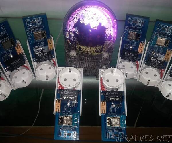
Old and new smartplug design:
In case of my old setup there was a Raspberry PI (which later got swapped out to a PC104 running NetBSD for industrial gradyness :P) -> Arduino -> 433 Mhz transmitter controlling ALL the wireless plugs it also introduced a single point of failure. What if the PI or Arduino (not likely) crashes, then all the home control is down.
This new design is completely decentralized (no blockchains yet :P), the only point of centralization is the wireless access point and if you worry about that you can just easily link multiple APs in a WDS net and the plugs will connect automatically to whichever is on and reachable. The wifi connection is extremely quick, the device connects and reachable in 1-2 seconds after powering on.
Extending the functionality:
As it is a way faster MCU than what the original “smart plug’s” had what else can be done with it:
-State detection: as I mentioned this was the main reason why I designed this circuit to always know if the device is ON or OFF, this value is stored constantly in a global variable and also written to the FLASH. This yields complete reliability over the old approach which was send the command X times to the “smartplug” via 433Mhz radio and hope for the best. Here in case of m2m communication the remote machine exactly knows if the device is reachable on https and can resend the command X times if it’s not and TCP/IP is guaranteeing reliability and automatic packet resend in case of lost/duplicated packets on wifi.
-Current metering: ACS712 was added for current measurement. Since the AC voltage is constant 230/110V we can determine the power (Watts) or the power consumption during time period (Watt Hours). I have left the PowerAVG calculation in from EOL, it could come handy in situations where you need to do the same thing (create alerts to see if a device is finished the work). Matter of fact this whole code is based on EOL, this project could easily replace it if wifi would go so far as my basement :P
-Keep state over restarts: Fortunately having such a great mini computer built in, this feature is now easily accessible. Device state can be saved in the FLASH: although the write cycle for ESP8266 is limited somewhere around 100K for the FLASH if you consider that the plug will be turned ON and OFF one single time every day and the state will be saved to the FLASH right away that is only 730 writes/year so it should not be an issue for the next 100 years.
-Programmable timer: I added this feature just to demonstrate that even if you add the functionality of a regular wireless plug + a timer plug together they still cannot compete with my project. Of course the ESP8266 can easily do programmed turn ONs and OFFs as well and it will be even more accurate because it sync with NTP every day while a cheap timer plug drifts off with seconds, minutes over time.
If you are still not satisfied with the functionality of the new plug a smaller Multi User Dungeon can be still implemented over TELNET :D
While having all these features is nice, I always implement manual control (at least a single push button to manually be able to turn the device ON or OFF).
Bill of materials
1X HLK-PM01 5V/0.6A isolated power supply
1X Wemos d1 mini
1X Wemos d1 mini relay shield
3X 300 ohm resistors
1X 10Kohm resistor
1X 2K2ohm resistor
1X RGB 4pin LED (Common Anode)
1X Push button
1X ACS712 20A
1X Fuse holder
1X 10A fuse
Wemos D1 mini hardware
Microcontroller ESP-8266EX
Operating Voltage 3.3V
Digital I/O Pins 11
Analog Input Pins 1(Max input: 3.2V)
Clock Speed 80MHz/160MHz
Flash 4M bytes
Length 34.2mm
Width 25.6mm
Weight 3g
Note: This board has one terrible inconsistent pinout, to make it a bit more consistent I have printed and using the Blue Arduino pinout everywhere.
The circuit board exported out in many different formats for your convenience. You can use a lot of online services to manufacture the board for you but I recommend EasyEDA (which was originally used to design the board) because they provide a great service with low prices, they deserve the support.
The first version of the board (shown on some picture), even after careful design was a failure (surprise, surprise), although the relay and current meter worked as expected the rest did not, which contributed to non working data pins on the bottom side of the board. Originally the G and B led legs were wired to the RX (3) and TX (1) pins:
//* CHANGE PIN FUNCTION TO GPIO *
//GPIO 1 (TX) swap the pin to a
GPIO. pinMode(1, FUNCTION_3);
//GPIO 3 (RX) swap the pin to a
GPIO. pinMode(3, FUNCTION_3);
//********
Sadly did not work and I had to go through lengths on debugging why is a so simple thing like turning on the led does not work after the board was manufactured. Same goes for the SWITCH pin which was originally pin 2. All these were brought around and up to the north side of the board where all seems to work fine. While the relay board connector pin 5, and the red pin 0 was working from the start (strange). Another 2 issues what I was not expecting is that there was an smd flyback diode on the bottom of the relay board, blocking the board to be able to completely pushed down to the motherboard, therefore in the next version I made a cut-out, also the whole board was extended in height because in the original the Wemos D1 mini would just overlap with the cutoff end of the HE smartplug making the extension box insertion more difficult.”