
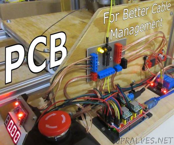
“A while ago i’ve made a custom desktop CNC mill. Since then i was upgrading it with new components. Last time i’ve added a second Arduino with 4 digit display to control RPM of my spindle using PID loop. I had to connect it with primary Arduino board with 5 wires, so they can communicate. But during my first test i broke a motor controller, so i’ve bought a new, more powerful one. It also had 5 more wires i had to connect. At this point the +5V pin on main board was split into 4 separate connections and i just didn’t feel like splitting the wire again. So i’ve done something else.”