
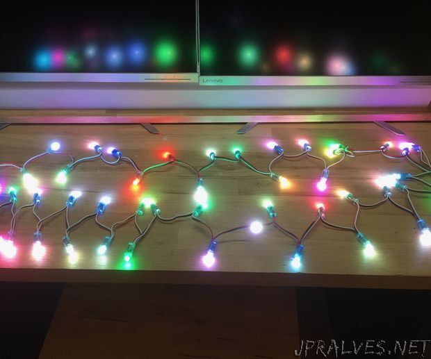
“Whilst browsing eBay I came across these strings of 50 addressable LEDs using the WS2811 chip, whilst I don’t think they are really designed to be used as fairy lights they do work well and they look awesome in the tree. It would also be possible to change the colours to make them suitable for any number of holiday themes. As it’s nearly Christmas I have gone with lots and red and green as well as some patterns that use a lot of random colours and of course what addressable LED project would be complete without a rainbow.
The Micro controller is an ATTiny 85 and there are 3 button that change the mode and the speed of the patterns in what I hope is a fairly intuitive way.
Im a big fan of the ATTiny85 as it works well with the Arduino IDE, its cheap and from my experience its quite a resilient chip.
The total cost per set is less than £15 and could easily be completed in a weekend with only basic tools.
Temporary parts needed:
Arduinouno or equivalent for programming the ATTiny
bread board and jumper wires for testing and programming the ATTiny
soldering iron and solder
hot glue gun
Parts used for the build:
I have included links to some of the items on Amazon to help identify them, its by no means the best place to purchase them and you should shop around.
ATTiny85 plus optional DIP 8 IC Socket ( https://amzn.to/2RgKpeJ )
1000uF capacitor * (see notes)
3 x 1 to 5 kΩ Pull down resistors.
1 x 300-500Ω resistor * (see notes)
1 piece of prototyping board ( https://amzn.to/2Rn4YGs )
USB to DC cable ( https://amzn.to/2BE2iyP )
DC Socket connector ( https://amzn.to/2TUFbHy )
Sting of addressable LEDs ( https://amzn.to/2Rm1Yds )
3 x momentary push switch
Project box ( https://amzn.to/2DTeTzA )
The 3 momentary push switches can be any kind you like but you may need to adjust your design to suit your switches. I had some with a longer button and 2 legs that makes them well suited to this project as I can poke them through a hole in the top cover and hot glue them in place from the bottom.
* This is copied from the Adafruit NeoPixel Uberguide and explains the need for the capacitor and resistor.
Before connecting NeoPixels to any large power source (DC “wall wart” or even a large battery), add a capacitor (1000 µF, 6.3V or higher) across the + and – terminals as shown above. The capacitor buffers sudden changes in the current drawn by the strip.Place a 300 to 500 Ohm resistor between the Arduino data output pin and the input to the first NeoPixel. The resistor should be at the end of the wire closest to the NeoPixel(s), not the microcontroller. Some products already incorporate this resistor…if you’re not sure, add one…there’s no harm in doubling up!
Other things to note:
Power use is always somthing you need to think about with addressable LEDs. To work out how much power you will need simply take the number of LEDs in your array and times it by 60 as each LED can draw 60ma
This is a string of 50 so 50X60 is 3000 or 3 amps whilst this is quite a lot of power its worth remembering that they will only use that much if on full brightness on all 3 colours. You can arrange your code to avoid this or use the setBrightness() command to limit it. in testing I have found my setup work well on a 2 amp power supply.
I would highly recommend reading the Adafruit NeoPixel Uberguide( https://learn.adafruit.com/adafruit-neopixel-uber… ) as it’s explains everything in much better detail than I can.”