
“Introduction
In this tutorial, we’ll cover DMX512 (Digital Multiplex with 512 pieces of information). Originally intended as a way to standardize communication among lighting dimmers, DMX512 has been adapted to control a variety of stage lighting and effects such as intelligent lights, gobos, lasers, and fog machines. DMX512 is even used in many architectural lighting scenarios (I’m looking at you Las Vegas). In this tutorial, we’ll go over what there is to know about how and when to implement DMX.
History
DMX512 was created in 1986 by an engineering commission for USITT (United States Institute for Theater Technology) as a way to control dimming channels on lights. In 1998, the ESTA began work in getting DMX to the point where it could be approved by ANSI and in 2004, DMX-512A was ANSI approved as the “Asynchronous Serial Digital Data Transmission Standard for Controlling Lighting Equipment and Accessories.”
Basic Definitions
Fixture/Slave: Any object that takes DMX input. Receives a full DMX packet, picks out and listens data relevant to itself (intelligent lights, gobos, lasers, and fog machines). Most Fixtures have an output channel that is simply a copy of the input.
Universe: A Universe consists of a set of fixtures all strung together reading the same data. A Universe contains 512 bytes of information, so the amount of fixtures in a universe will depend on how many bytes of data are needed to address each fixture.
Controller: Creates and sends DMX data to one or more Universes. Usually, this a large board with many knobs and sliders, however, a simple PC can be used as a DMX controller.
Hardware Layer
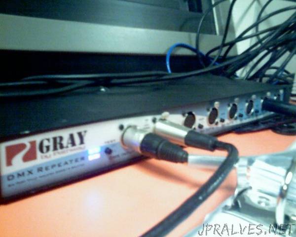
DMX512 is typically employed over relatively long distances due to the distance between the lighting booth and stage. The further a signal is sent, the longer distance you have available to pick up stray electromagnetic interference from the surrounding area. Combine this with the fact that DMX is usually used in electrically noisy environments and we have to settle on a solution that is relatively noise free, so DMX employs RS-485.
Signals like this are interpreted by reading the difference between one wire with the data (D+), and another wire with the inverse of the data (D-). Since we are reading the difference, we call this a differential signal. Differential signals like RS485 pick up noise almost equally along the two signal lines, this keeps the difference between the two signals the same. Since we read the difference between the two signals, it’s easy to communicate over long distances (The DMX standard recommends a maximum run of a thousand feet, although RS-485 is rated for 4,000 feet).
DMX data is typically transferred over an XLR-5 cable, although occasionally, DMX capable XLR-3 cables are also used. RS-485 only requires 3 lines, ground, Data+, and Data-; and in many applications, this is all that was used. However, an additional pair of data lines was added to allow for future growth, requiring the XLR-5 cable. These connectors and their pinouts are shown below.”