
“I’m working on an I2C project, but I don’t have a sampling oscilloscope and I need to see what the heck is going on, so I put together this quick and dirty I2C sniffer sketch.
You connect two digital pins on the Arduino to the I2C bus lines SDA and SCL, and Arduino ground to I2C ground. The digital pins on the Arduino must be on PORTD, which are pins 0 through 7. It’s probably a good idea to avoid the serial lines, which means you should use any two pins between 2 and 7.
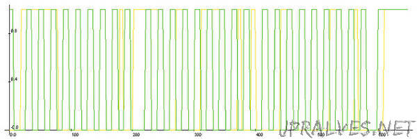
It captures the data (within a certain time window) and then it sends CSV-formatted output to the serial port. You can then take this data and plot it to get an idea of what’s going on on your I2C bus. Naturally, you could expand this to sniff other bus-types, like 1-wire or SPI, provided the signalling rate is low enough. For SPI you might trigger off the SS line. This code samples at about 2Msps on an Arduino running at 16MHz — that figure is derived from the fact that it records approximately 20 samples per 100kbit/s clock cycle.
This code runs a “one-shot” capture, meaning that it only captures data once and then dumps it to the serial port. It starts capturing when it detects the SDA line has gone low. it does not check the SCL line (as a proper start condition detector would).
You can adjust the capture window to suit your needs, though bear in mind that the ATMega328 only has 2k of RAM, so values approaching 2000 may not work so well. A value of 250 is long enough to catch one byte sent over I2C at the 100 kbit/s standard rate. The sampled data is good enough to show you the sequence of events.
If you need very specific, time-aligned data, you should use a logic analyzer or sampling oscilloscope.
For plotting, I recommend LiveGraph, which is super easy to use and runs in Java, so it’s portable.
The code is CC-BY-SA 3.0 and unsupported. Use at your own risk.”