
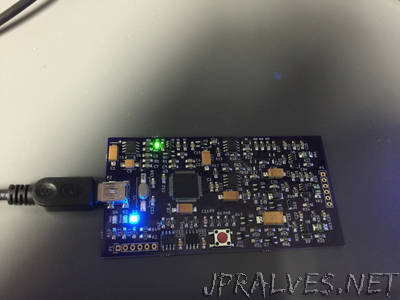
“After using the Microchip tools to program and debug the projects I work on, I wondered about creating my own programming/debugging module that I could put on my own boards – just like Microchip does with their starter kits and such. As I became more interested in that idea, I began to search the web to see if anyone else had already done something similar. Initially, I found lots of posts regarding the 2nd version of the Pickit – the Pickit 2, but not as much regarding the latest version – the Pickit 3 – which is what I need to program the 32 bit pic processors that I am using. After a while I came across a post – From this blog. This Individual had created his own version of the Pickit 3 and had posted his method for doing so. I was excited to see some real information about the process, and set about determining how I would do the same, now that I knew someone else had verified that it would work. The version that was built on the blog linked above, was done so on a protoboard using a variety of components, and was completely hand-wired. As impressive as that is, I was looking for something a bit sleeker – especially since I was looking at some point to modularize it and use it on other designs. I decided that I would design my project to use surface mount components and a purpose designed PCB. With that in mind, I set out to create my schematic. After looking at the one from Hendrik’s blog post above, and also studying the actual Microchip pickit 3 schematics that are publicly available in the documents released by Microchip, I came up with the following schematic. It is pictured below, and here is a link to the full-sized PDF: My Schematic”