
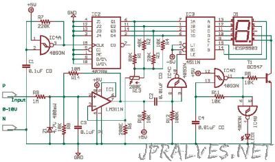
“I wanted to design a logic probe as a tutorial, but there were many good ones in the web so i have tried to design a single digit voltmeter. This circuit is a design, i am unable to test it now, later if i test it and find mistakes i will update this page. You can help me by pointing out the errors. First bear it in mind that it is a single digit voltmeter which is 0-9 counts only on the positive side, that is it can measure +0 to +9V DC +/- 1V error. That may not be practical for the cost of the components above. It may be used as a toy logic probe. The reason for the circuit is not for usage, but to give design ideas. The methodology used is Gut Feel - Thumb Rule method. “