
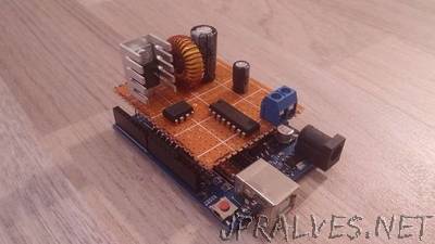
“In this Instructable, I will show my Arduino-controlled buck/boost/inverter converter. And what means that “true” in the title, you ask? Well, you have probably already seen a tutorial where somebody just connected a transistor to the PWM output of an Arduino along with a few other parts and called that a buck/boost/inverter converter (for example here). I admit it, I also used it once in my AVR Universal Charger. It works OK when your load is not changing, but if your load rapidly changes, the controller can’t react fast enough and this can lead to a very dangerous over-/under-voltage. So generally this is a very bad idea. A much better way is to use a chip designed exactly for this purpose. Here, we will use TL494 from Texas Instruments. You can find this chip in most computer power supplies or even classical converters. But did you know that we can control the output of the chip from an Arduino? Basically our Arduino will tell the chip what output voltage and max current we want and the chip will do all the hard work, so we do not have to care about Arduino latency. Also, because this chip is analog (compared to digital Arduino), it is superior as far as accuracy goes.”