
Espruino is a JavaScript Interpreter for Microcontrollers that is designed to make development quick and easy. The Espruino interpreter is firmware that runs on a variety of different microcontrollers, but we also make Espruino Boards that come with the interpreter pre-installed and are the easiest devices to get started with.
However Espruino itself isn’t just the interpreter firmware or hardware - there’s also the Web IDE, command-line tools, documentation, tutorials, and modules which form a complete solution for embedded software development.
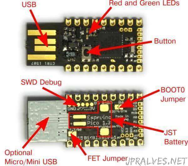
Pico
The Pico is designed to plug right into you computer’s USB type A connector, or a USB extension lead. The components (not the text) should usually be facing upwards (so the 4 gold strips are facing the plastic in the USB socket).
Specifications
- 33mm x 15mm (1.3 x 0.6 inch)
- 22 GPIO pins : 9 Analog inputs, 21 PWM, 2 Serial, 3 SPI, 3 I2C
- All GPIO is 5 volt tolerant (Arduino compatible)
- 2 rows of 9 0.1” pins, with a third 0.05” row of 8 pins on the end
- On-board USB Type A connector
- Two on-board LEDs and one button.
- STM32F401CDU6 32-bit 84 MHz ARM Cortex M4 CPU
- 384kb flash, 96kb RAM
- On-board 3.3v 250mA voltage regulator, accepts voltages from 3.5v to 16v
- Current draw in sleep: < 0.05mA - over 2.5 years on a 2500mAh battery
- On-board FET can be used to drive high-current outputs
- Rev 1v4: 500mA polyfuse on board
- Rev 1v4: CE and RoHS certification
PinOut
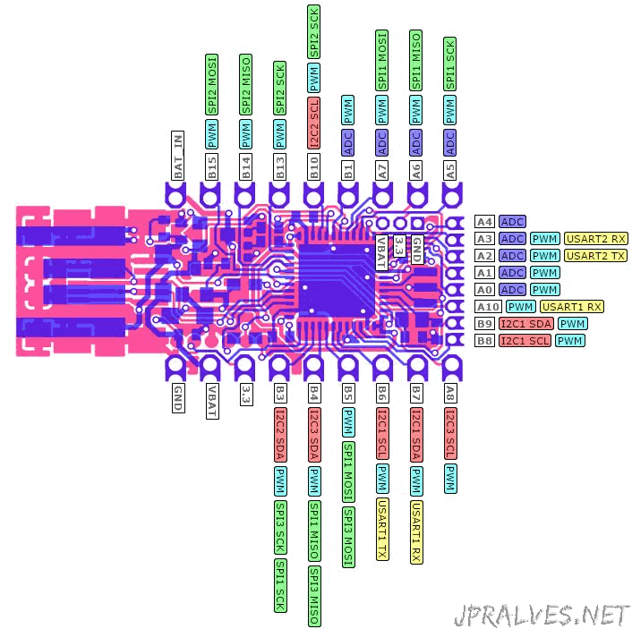
- Purple boxes show pins that are used for other functionality on the board. You should avoid using these unless you know that the marked device is not used.
- ! boxes contain extra information about the pin. Hover your mouse over them to see it.
- 3.3v boxes mark pins that are not 5v tolerant (they only take inputs from 0 - 3.3v, not 0 - 5v).
- 3.3 is a 3.3v output from the on-board Voltage regulator.
- GND is ground (0v).
- VBAT is the battery voltage output (see the Espruino Board Reference).
- ADC is an Analog to Digital Converter (for reading analog voltages)
- PWM is for Pulse Width Modulation. This creates analog voltages from a digital output by sending a series of pulses.
- SPI is the 3 wire Serial Peripheral Interface.
- USART is a 2 wire peripheral for Serial Data.
- I2C is the 2 wire Inter-Integrated Circuit bus.
PINS NOT ON CONNECTORS
- A9 USB PWM USART1 TX
- A11 USB PWM USART6 TX
- A12 USB USART6 RX
- A13 JTAG
- A14 JTAG
- A15 JTAG PWM
- B0 ADC USB PWM
- B2 LED1 BOOT1
- B12 LED2
- C13 BTN1
- C14 OSC RTC
- C15 OSC RTC
- H0 OSC