
ESP8266E is among the most integrated Wi-Fi chips in the industry. Measuring just 5mm x 5mm, ESP8266EX requires minimal external circuitry and integrates a 32-bit Tensilica MCU, standard digital peripheral interfaces, antenna switches, RF balun, power amplifier, low noise receive amplifier, filters and power management modules - all in one small package.
ESP8266
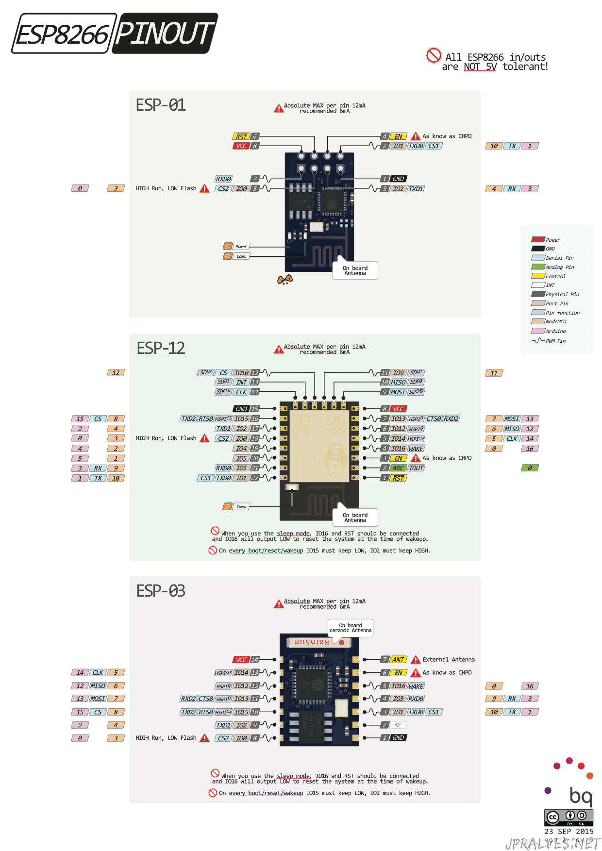
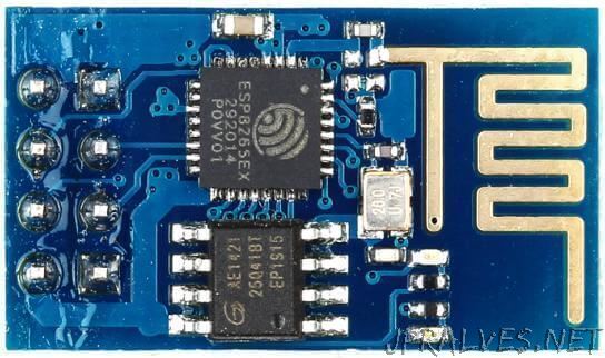
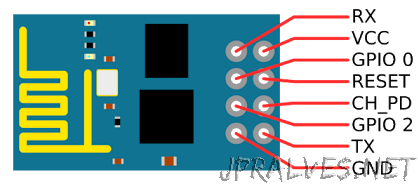
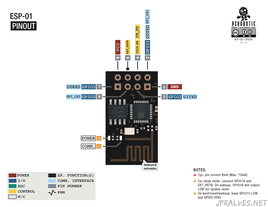
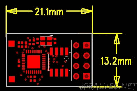
ESP-01
PinOut
Dimensions
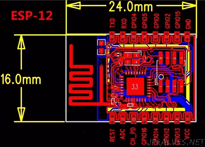
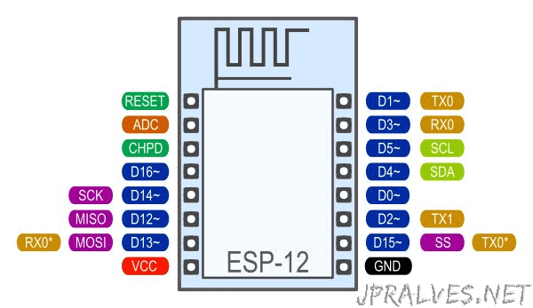
ESP-12
Dimensions
PinOut
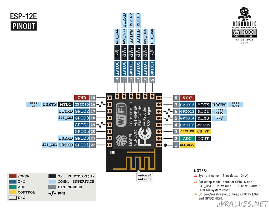
ESP-12E
PinOut
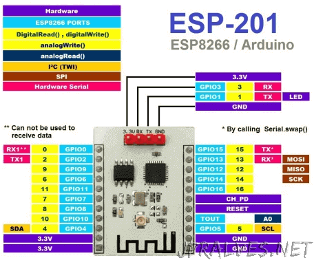
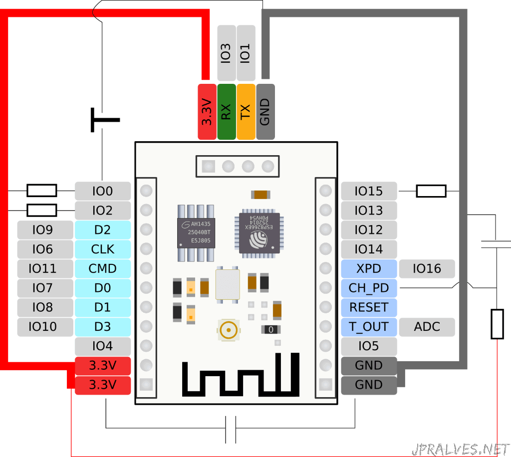
ESP-201
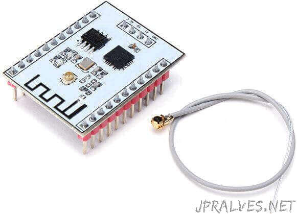
Originally named as ESP-12 this module has come to popularity as ESP-201 after the name clash had been discovered. In good old BASIC line adressing style the creators apparently wanted to make sure that no other name clash would occure and added a safety distance to the numbering scheme;-)It is currently my preferred module for prototyping since it is breadboard friendly and offers similar access to the chip pins as the ESP-12 does. I say breadboard friendly with two remarks: the four pins at the head of the module keep you from directly plugging the module into a breadboard. But you can easily bend them to ninety digrees or unsolder them and place them on the upper side of the module. The second note is that the module itself hides many pins of the bread board for direct access and leaves only one row visible on each side of the module. If you need more you will have to extend a 5-pin row by connecting it to annother row on your breadboard. The board comes with a printed PCB antenna but also with a connector for an external one. This makes this module also a perfect candidate if you need to bridge a longer distance with your Wifi module. You can then easily replace the package wire antenna with a high-gain antenna and improve the sensitivity even farther.
PinOut
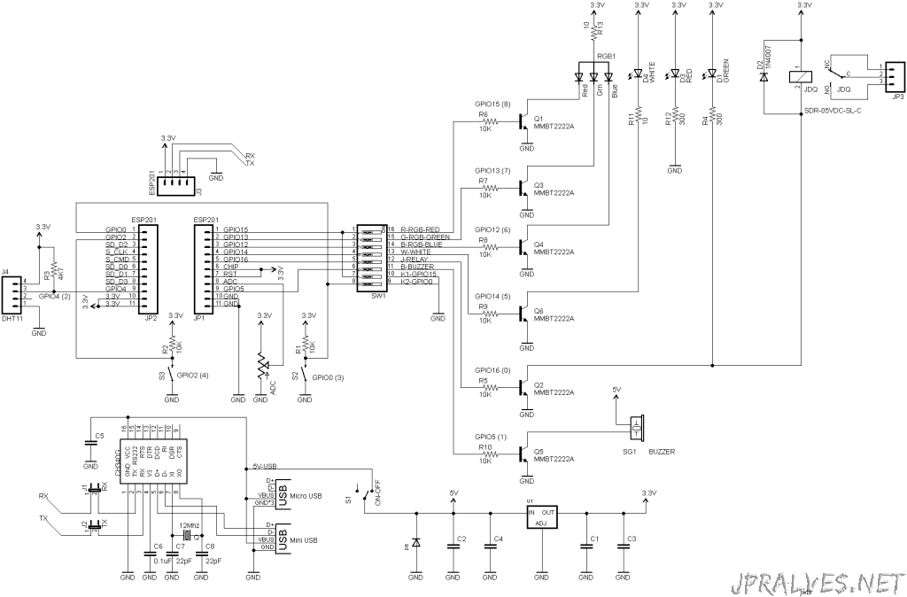
ESP8266 development SDK
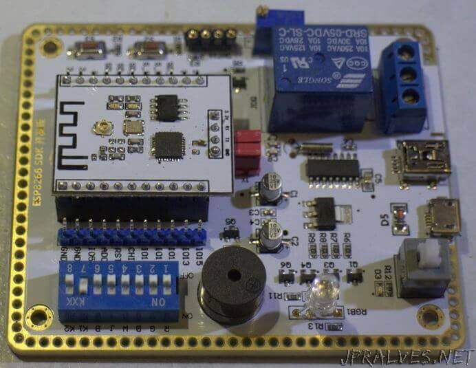
PinOut
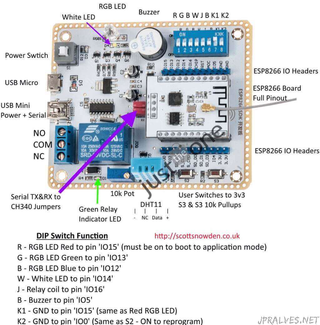
The switch controls are as follows:
- R – RGB LED Red to pin ‘IO15’ (must be on to boot to application mode)
- G – RGB LED Green to pin ‘IO13’
- B – RGB LED Blue to pin ‘IO12’
- W – White LED to pin ‘IO14’
- J – Relay coil to pin ‘IO16’
- B – Buzzer to pin ‘IO5’
- K1 – GND to pin ‘IO15’ (same as Red RGB LED – holding ON while powering is same as R off i.e. will not enter application mode)
- K2 – GND to pin ‘IO0’ (Same as S2 – switch ON when powering to enter reprogramming mode)
- S2 – GND to pin ‘IO0’
- S3 – GND to pin ‘IO2’
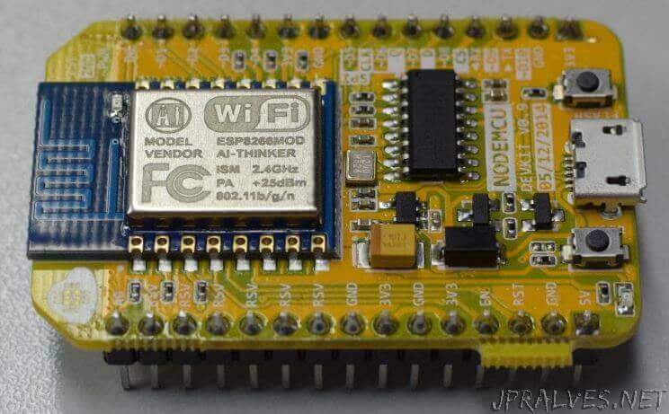
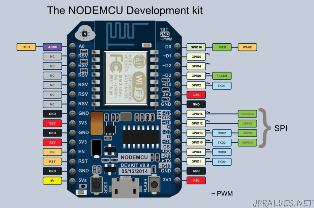
NodeMCU 0.9
PinOut
Links
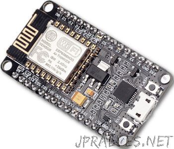
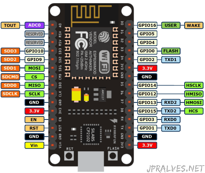
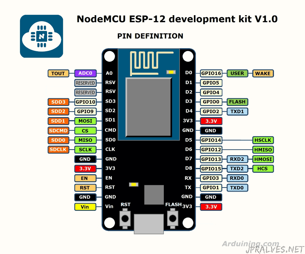
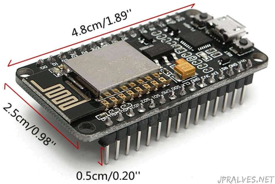
NodeMCU 1.0
Specifications
- Wi-Fi Module – ESP-12E module similar to ESP-12 module but with 6 extra GPIOs.
- USB – micro USB port for power, programming and debugging
- Headers – 2x 2.54mm 15-pin header with access to GPIOs, SPI, UART, ADC, and power pins
- Misc – Reset and Flash buttons
- Power – 5V via micro USB port
- Dimensions – 49 x 24.5 x 13mm
PinOut
Dimensions
Links
ESP8266-D1
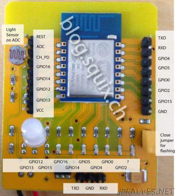
ESP8266 Evaluation Board ESP-12
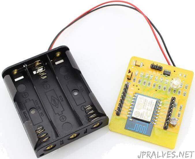
This development board is a ESP8266 ESP-12 full evaluation board, The core ESP8666 module was mounted on a PCB with all the GPIO broken out.The board is powered by 3 x AA cells, and an onboard regulator ensures a neat 3.3V supply for the ESP8266. Furthermore, each GPIO has an LED connected so you can quickly test your code without connecting external hardware, and a LDR to test the ADC.
Specifications
- All usable pins are available on board
- Metal casing
- Three channels PWM
- Six I/O pins
- One ADC
- One high speed serial port
- low power consumption, suitable for battery-powered applications
- Single 3.3 V power supply
PinOut
ESPDuino
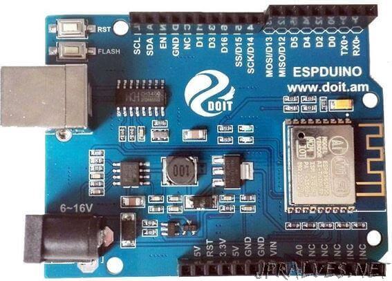
ESPduino is developed by Doit company based on the ESP8266 ESP-13, which can be compatible with Arduino UNO R3 development board. By using the ESP8266 WiFi and MCU,ESPduino supports WiFi. Compared to the traditional Arduino UNO development board, users don’t have to buy another WiFi development board.
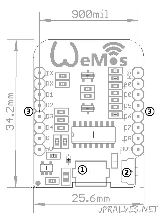
WeMos-D1 mini
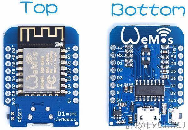
Specifications
- Microcontroller: ESP-8266EX
- Operating Voltage: 3.3V
- Digital I/O Pins: 11
- Analog Input Pins: 1(Max input: 3.2V)
- Clock Speed: 80MHz/160MHz
- Flash: 4M bytes
- Length: 34.2mm
- Width: 25.6mm
- Weight: 10g
Dimensions
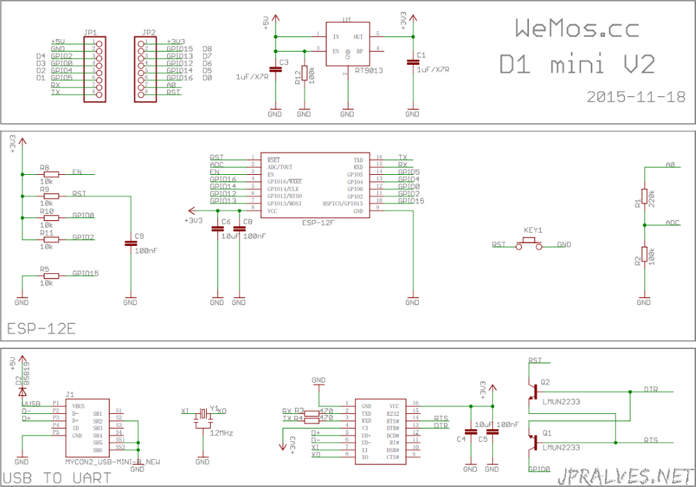
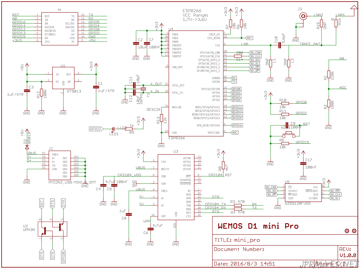
Schematic
Links
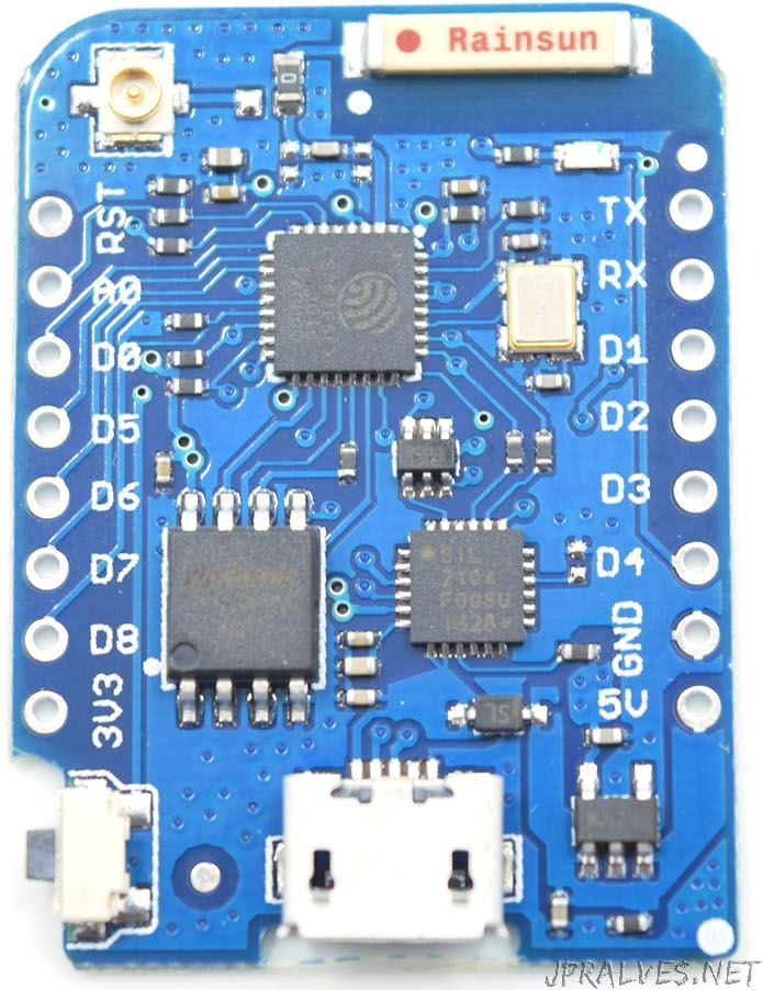
WeMos-D1 mini Pro
Specifications
- 11 digital input/output pins
- Interrupt/pwm/I2C/one-wire
- 1 analog input(3.2V max input)
- 16M bytes(128M bit) Flash
- External antenna connector
- Built-in ceramic antenna
- New CP2104 USB-TO-UART IC
- Same size as D1 mini, but more light
Technical specs
- Microcontroller: ESP-8266EX
- Operating Voltage: 3.3V
- Digital I/O Pins: 11
- Analog Input Pins: 1(Max input: 3.2V)
- Clock Speed: 80MHz/160MHz
- Flash: 16M bytes
- Length: 34.2mm
- Width: 25.6mm
- Weight: 2.5g
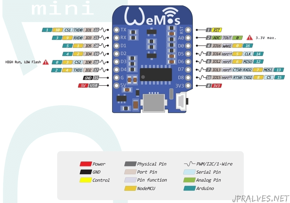
Pins
| Pin | Function | ESP-8266 Pin |
|---|---|---|
| TX | TXD | TXD |
| RX | RXD | RXD |
| A0 | Analog input, max 3.3V input | A0 |
| D0 | IO | GPIO16 |
| D1 | IO, SCL | GPIO5 |
| D2 | IO, SDA | GPIO4 |
| D3 | IO, 10k Pull-up | GPIO0 |
| D4 | IO, 10k Pull-up, BUILTIN_LED | GPIO2 |
| D5 | IO, SCK | GPIO14 |
| D6 | IO, MISO | GPIO12 |
| D7 | IO, MOSI | GPIO13 |
| D8 | IO, 10k Pull-down, SS | GPIO15 |
| G | Ground | GND |
| 5V | 5V | - |
| 3V3 | 3.3V | 3.3V |
| RST | Reset | RST |
Schematic
Links
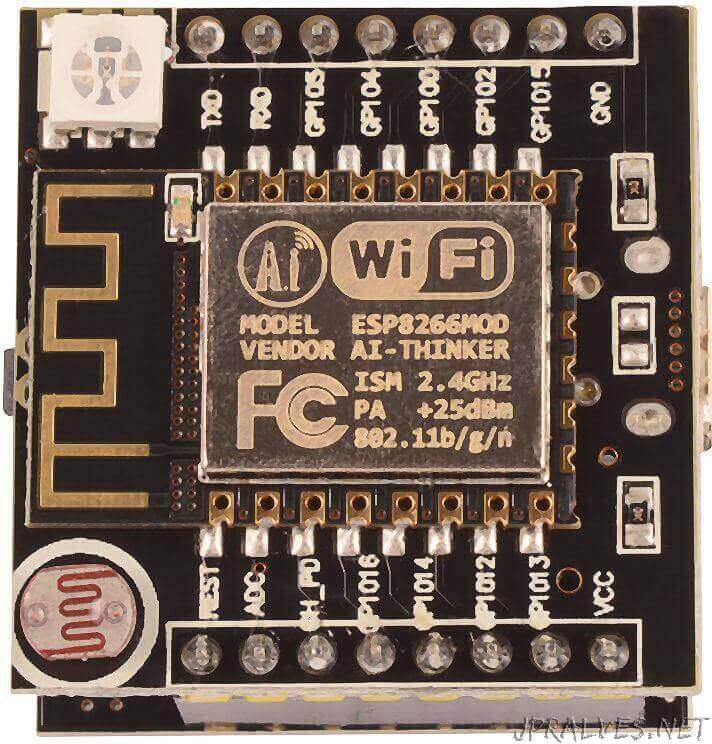
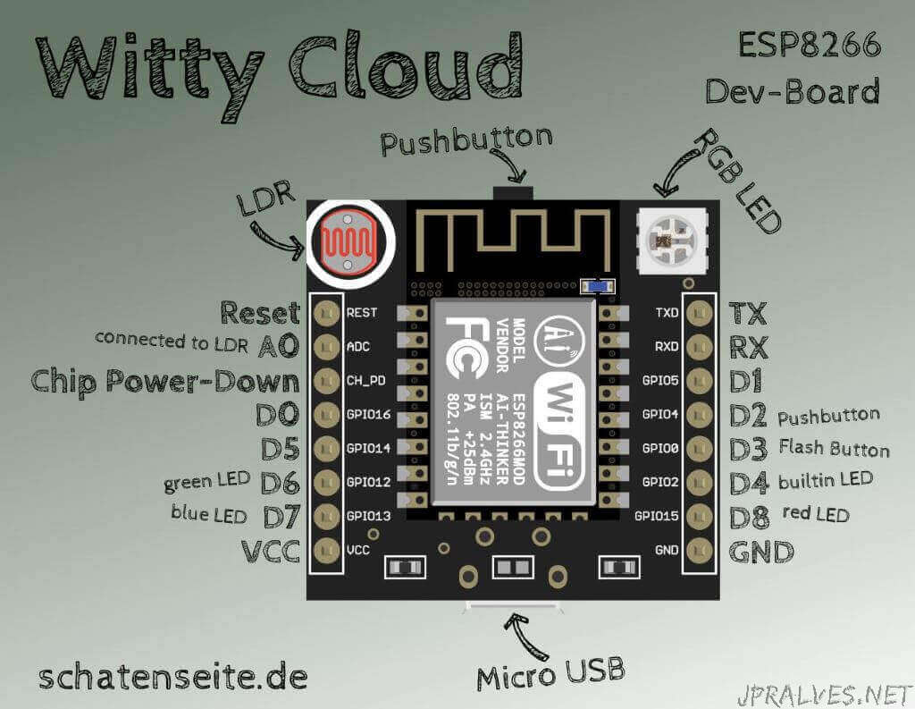
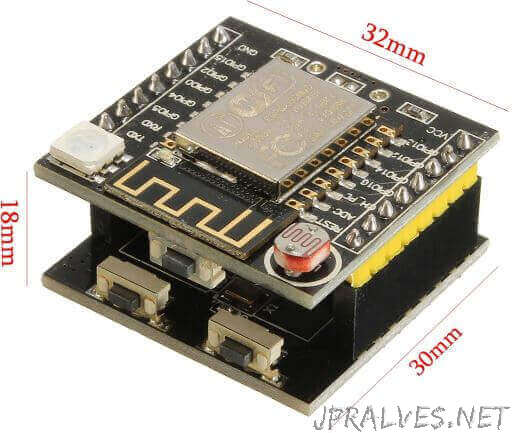
Gizwits Wifi Witty ESP8266 ESP-12F
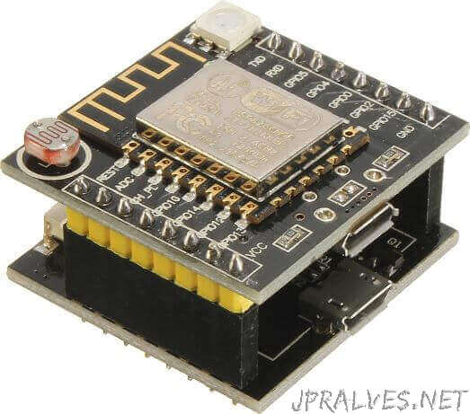
This small Wifi transceiver is the perfect solution for home Automation and IoT applications. It can be the replacement of your NRF24L01, it can talk to your Wifi router directly through the UART MCU’s (Rx, Tx).The ESP-12 module is one of the most complete module in the ESP family. It allows you to use the biggest amount of pins of all of them. You can program this module to work standalone with the Arduino IDE or with LUA as NodeMCU.It has an LDR and a WS2812 LED already on board for your projects. The board comes with a CH40 micro USB module to program it.The ESP8266 highly integrated chip, including antenna switch balun, power management converter, so with minimal external circuitry. The system is equipped with ESP8266 manifested leading features are: energy saving VoIP quickly switch between the sleep / wake patterns, with low-power operation adaptive radio bias, front-end signal processing functions.
Specifications
- ESP-12F WIFI Wireless Transceiver Module + Breakout Pre-soldered
- CH340 Micro-USB interface motherboard.
- LDR Light Sensor on board
- WS2812 Led on board
- 3x tactile buttons (1x in the Witty board and 2x in the CH340 board)
- Supports 3 modes: AP,STA,AP+STA
- Dimensions: 32mm x 30mm x 18mm
- Micro USB connection for power and/or programming
PinOut
Dimensions
Links
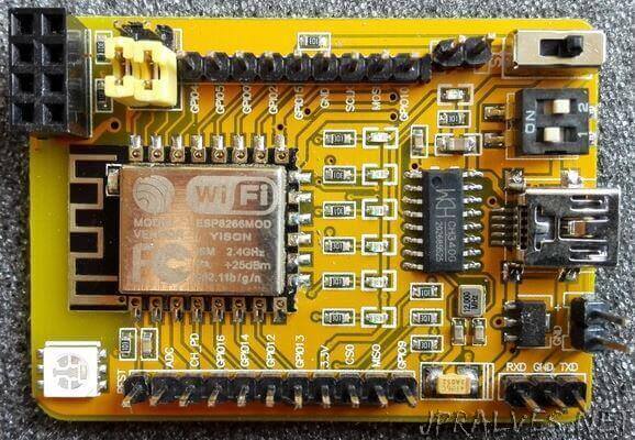
ESP-01/ESP-202 Development Board
ESP8266 onboard test panel USB to TTL, can be carried out on the ESP - 202-01 and ESP AT the firmware of the test, AT the same time can be compatible with the ESP - 07 12 12 e. Can not only test the AT the firmware, but also can be used when the development board, do IOT firmware development, for customers to test. If you want to play NodeMcu Lua WIFI development, as long as the brush firmware NodeMcu firmware can also be the development of Lua.
Features
- 100% brand new and high quality
The test plate is simple to use the AT command video tutorial. Please follow the following steps.
Use your cell phone and install IOT.APK.
- Short circuit hat connect to the electric flash model, take off and then go to the normal state.
- Put on the battery, use your cell phone to search the ESP-202 wifi name
- Plus this router.
- After passing, you can control the module of the cell phone.
Specifications
- Color: Yellow
- Size: 55mm x 38mm
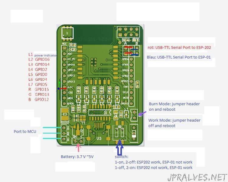
LED Pinout
’’’On the board the labels for GPIO4 and GPIO5 are switched!’’’
| LED | GPIO | Pin |
|---|---|---|
| on module | 1 | |
| 1 | 16 | 16 |
| 2 | 14 | 14 |
| 3 | 2 | 2 |
| 4 | 0 | 0 |
| 5 | 5 | 4 |
| 6 | 4 | 5 |
| RGB/red | 12 | |
| RGB/blue | 13 | |
| RGB/green | 15 |
Pin here stands for the pin number to be used in code to access these LEDs.
Example
int LEDS[6] = { LED_BUILTIN_1, LED_BUILTIN_2, LED_BUILTIN_3, LED_BUILTIN_4, LED_BUILTIN_5, LED_BUILTIN_6 };

void setup() {
  for(int x=0; x<6; x++) {
    pinMode(LEDS[x], OUTPUT);
  }
}

void loop() {
  for(int x=0; x<6; x++) {
    digitalWrite(LEDS[x], LOW); // switch led on
    delay(100);
    digitalWrite(LEDS[x], HIGH); // switch led off
    delay(10);
  }
}