
“In this project, we’ll guide you through designing a low-noise audio amplifier using the 2N3906 transistor.
Circuit Design:
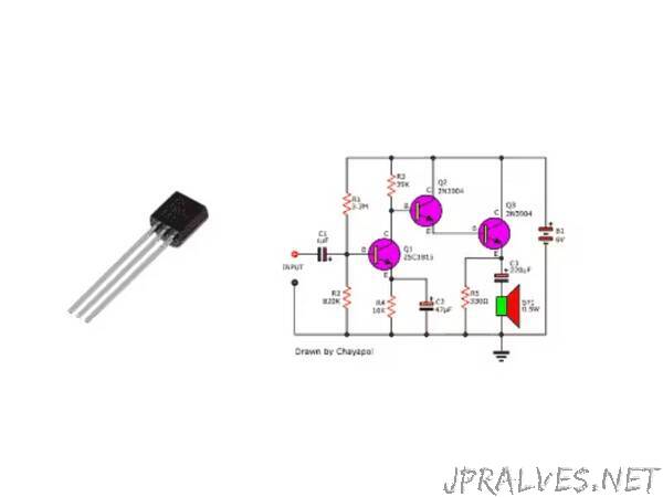
1. Biasing Circuit:
Connect the emitter (E) of the 2N3906 transistor to the ground.
Connect a resistor (RE) from the emitter to the base (B) of the transistor (e.g., 100Ω).
Connect a resistor (RB) from the base to the positive supply voltage (e.g., 10kΩ).
2. Input Coupling Capacitor:
Connect a capacitor (C1) between the audio input source and the base of the transistor (e.g., 10µF electrolytic capacitor).
3. Output Coupling Capacitor:
Connect a capacitor (C2) between the collector (C) of the transistor and the speaker/headphones (e.g., 10µF electrolytic capacitor).
4. Decoupling Capacitor:
Connect a capacitor (C3) between the collector of the transistor and the positive supply voltage (e.g., 0.1µF ceramic capacitor).
Testing
Apply an audio signal to the input of the amplifier and connect a speaker or headphones to the output. Verify that the amplifier amplifies the audio signal with minimal distortion and noise. Adjust resistor values if necessary to optimize performance.
Conclusion
Designing a low-noise audio amplifier with the 2N3906 transistor provides a simple and effective solution for amplifying audio signals with high fidelity. This project demonstrates the use of the 2N3906 transistor in audio applications and showcases its ability to deliver clear and crisp sound reproduction.”