
“Hello. In this instructable, I would like to share with you the joy (and a little bit of struggle) of designing my own uninterruptible power supply. I will try to present you the whole design process, my thoughts, mistakes, and results.
Supplies:
For the design, you will need any software that allows you to create electronic schematics and layouts.
For prototypes, you need a soldering iron, cuprextit boards, wires, solder, flux, and the components listed later.
For measurement, you need a multimeter, an oscilloscope, and a thermometer (or thermal camera).
Step 1: What Is an Uninterruptible Power Supply?
An uninterruptible power supply (UPS) is a device that ensures that the load stays powered even if the grid blacks out. On a very simplified diagram, you can see how the direct current standby UPS works.
When there is power on a grid, current flows first via an ACDC converter and then via a DCDC converter to the output. The battery is charged to its full capacity and is prepared for a power outage.
When a power outage occurs, the battery replaces the ACDC converter and powers up the rest of the circuitry.
The device must also have some kind of detection circuit implemented, as well as protections and charging management.
Step 2: Lead-Acid or Li-Ion Battery?
I needed a specific type of UPS that would fit on the maximum 13x17 cm printed circuit board and would be max. 4.5 cm high to fit into my modular system. I also needed it to provide two selectable voltage rails: 12V and 5V. Both should handle 2 Amps, and the battery should provide this power for at least 1.5 hours.
Since the beginning, I knew that the lead-acid batteries would not be usable in this project. They have a low power density compared to lithium-ion batteries and are sold in quite large dimensions, which won’t fit into my system.
Let’s assume that UPS will have 80% power efficiency. 2 Amps at 12 V per hour make 24 watt-hours. With 80% efficiency, at least a 30 Wh battery is needed. If I use four 18650 types of cells, this should provide me with around 40 Wh total with a good reserve, accounting for the battery degradation over time. A lead-acid battery with equal energy would be much heavier and larger in volume.
Step 3: Schematics
The schematic shown here is final, but it went through multiple edits and adjustments. I will briefly explain each section (block) and what they do.
1: Input protection and 24V ACDC adapter: UPS can be powered either from the grid or from an external DC supply. In the case of grid power, there is a fuse and varistor, which protect the system from overvoltage or short circuit. Power is converted via the isolated converter AMEL45-24SJZ, which can provide 45 W and has a peak efficiency of 86%. Switch SW1 is a toggle switch that can enable or disable the whole UPS system, including the battery. Q6 and additional components serve as reverse-polarity protection.
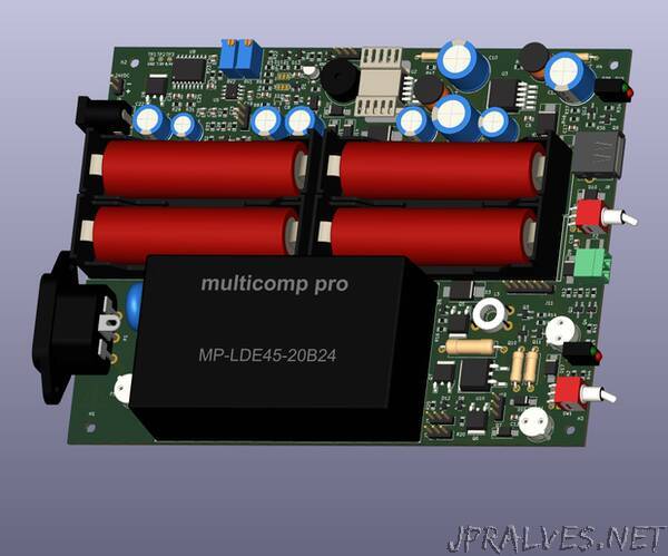
2: Battery charger, battery pack, and battery management system (BMS): The battery pack consists of four 18650 batteries (BT1–BT4), connected in series (4s configuration). There is an external BMS system that must be connected via a connector. The battery pack is protected via a 3.15-A fuse.
When designing the charger, I wanted to avoid specialized integrated circuit chargers. Due to component shortages, it might be a problem in future designs. Therefore, I designed a simple one-stage constant-current charger with analog control. It works as follows: Battery voltage is sensed via U5A and U5B, which are configured as comparators. If the battery pack voltage is below 15.8V, the U5A output goes high and sets the CD4043 latch, which enables the linear charger U10. When the battery pack voltage is higher than 16.8 volts (4.2 volts per cell), the latch is reset via the U5B comparator, and charging is stopped. This circuit is simple and reliable. Since there is no need for very fast charging, the pack is charged only with 120 to 240 mA, and there is no need for the CC-CV phase.
3: Control logic: Control logic makes sure that the switching from the grid to the battery happens as fast as possible. U1 is constantly sensing the scaled input voltage, which is compared to the stable voltage generated by the 5V regulator. When the ACDC converter voltage falls below a certain threshold, a pass transistor Q5 is shut down and a bidirectional switch Q10–Q11 is enabled. BZ1 is a simple buzzer that, with a short beep, lets the user know that a power outage has occurred.
4: 12V, 2A DCDC Converter: This is the DCDC converter, which provides my primary output power. I used the IC AP1501-12-K5G, which is quite available and a very simple converter. L1 and D4 were selected to handle 2A of continuous current, and the output is protected by a PTC fuse and a transient voltage suppressor. SW2 is a toggle switch that will enable either a 12V or 5V converter.
5: 5V/2A DCDC Converter with USB Output: The 5V converter is topologically the same as the 12V one, but it uses a different control IC (AP1501-50K5G-13). The input capacitors of both converters were selected to obtain a low output ripple voltage. Both converters also have the minimal load needed for regulation (R17 and R18).
6: 12V and 5V linear regulators: linear regulators provide power for control circuitry and also the reference voltages for comparators. I originally wanted to use only a single 5V regulator, but battery charger circuitry needed a higher voltage for proper operation.”