
“Morse Code, often referred to by Ham Radio folks simply as CW, is usually sent using a hand operated switch called a ‘Key’. You’ve seen these somewhere, the old telegraph key. Another device called a ‘Keyer’ can automatically generate the long and short tones, the dashes and dots Morse is comprised of. A keyer will use a set of paddles, two parts that sit between your index finger and thumb. Press one and a series of long tones is generated, press the other and a series of short tones is generated.
These two methods are by far the most common way of operating a transmitter to send Morse over the air. They require a bit of practice to get clean code. Orderly tones with proper spacing between them, slightly longer spacing between letters, and even longer spacing between words.
But what if someone has a problem with their hands, loss of dexterity with their fingers, injury, stroke or disease that prevents them from using a key or paddles? Why not use the voice?
Every CW operator I’ve ever met can speak Morse code. We say the words, “Dah” for a dash, and “Dit” for a dot. The naturally spoken length of each corresponds to the correct ratio in length of the long and short tones of proper code. And speaking is one of the most natural things we do.
Sure, there are other options. A puff key, consisting of a straw that’s blown into to ‘key’ the transmitter. A foot switch. A squeeze switch if you can still clutch your fist reliably. However, these require retraining your brain, can be clumsy at first, maybe hard to ever get clean code with.
So I set out to design a voice keyer. A simple method of following the voice of spoken Morse and keying a transmitter right along with it.
I had a few design goals in mind. Keep the circuit simple and cheap. Easy to build and reliable. In order to produce the cleanest keying possible, I decided to do the work in software with an arduino, giving me precise control over the keying for nice clean transmission.
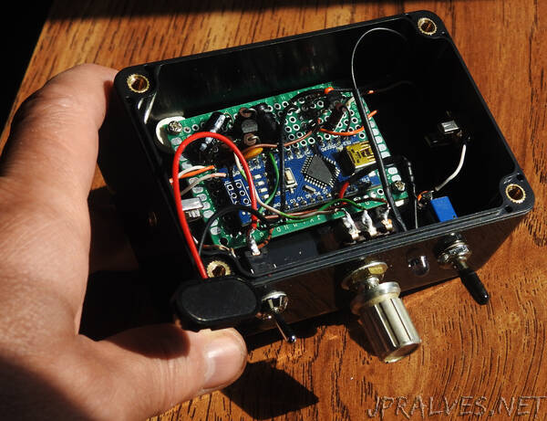
Circuit description:
The circuit can be powered from a 9 volt battery, it only draws around 30 ma when idle. The input voltage can be from 7 to 12 volts since we use the voltage regulator on the arduino to provide 5 volts for the rest of the circuit.
Most headsets use a condenser microphone element which will have a built in preamp that needs a small amount of power to operate. R1 provides that power. C1 then blocks the DC but passes the audio to a simple transistor amplifier.
Q1 is the amplifier. It takes the small, 80-120 millivolt audio from the mic and amplifies it to around 4 volts peak to peak. D1 then clamps the negative swings, leaving us with a purely positive waveform. C3 then smooths the audio to a less choppy DC voltage the arduino can sense and operate on.
R5 is a linear 10K pot that allows us to set the sensitivity of the mic. You don’t want room noise interfering after all.
Q2 is a simple transistor switch for keying the radio in CW mode. D2 provides transient protection from any spikes that might come in from the radio. Likewise C4 provides a bit of RF protection, bleeding any stray RF to ground.
SW2 cuts off the keying action when it’s not needed. i.e. while adjusting the sensitivity pot, or talking to someone else in the room, etc.
The LED performs two functions. It’s a power light, at around 40% illumination, and switched to full brightness when the radio is keyed as a visual indicator. It’s also useful for setting the sensitivity without actually transmitting.”