
“We use the compounded knowledge we have gained in class to make an autonomous RC car that follows a lane and stops at a red box stop.
This autonomous car is based on raja_961’s “Autonomous Lane-Keeping Car Using RaspberryPi and OpenCV” project on Instructables (https://www.instructables.com/Autonomous-Lane-Keeping-Car-U sing-Raspberry-Pi-and/) as well as Team ReaLly BaD Idea’s car and code from the previous session of ELEC 424 (https://www.hackster.io/really-bad-idea/autonomous-path-following-car-6c4992). The car follows a path guided by two blue lines, which starts out as a straight path but curves at the end. When the car detects red tape on the path, it stops momentarily before continuing again.
In order for the car to run through the course smoothly, we needed to tune some important values that affected vision, steering, and speed. The resolution of the camera needed to be chosen so that the blue lines of the lane could be seen and the slope of each line could be determined by the OpenCV modules in our main Python code. Thus, we chose the maximum resolution supported by the camera that was also small enough to not hinder the performance of the program by making the processing very time and computation intensive; this resolution ended up being 160x120. As for the proportional and derivative gains of the steering, we found that the constants (kp was 0.095 and kd was 0.0095) used in Team ReaLly BaD Idea’s code worked well for our car as long as the base PWM for each turn was low enough that the car did not turn too quickly but high enough that the car did not turn too slowly. Additionally, the ability to turn was helped by the speed of the car moving forward, which was affected by the encoder program, which slowed down or sped up the drive depending on the timing measured between the wheel spokes breaking the encoder light beam.
The stop box was detected through the use of the OpenCV module in Python. It depended on the value we gave the code for the color of red (which came from Team ReaLly BaD Idea’s code), and this caused a few issues early on because our camera only reacted to red tape (rather than the lighter construction paper). In the main loop, the OpenCV module was used to check until most of the camera’s frame was red, and this was done every frame. Once the first stop box was detected, a boolean caused the car to stop, and the rate at which the second stop box was checked for was slowed down to every 3 frames (this rate began 200 frames after the first stop sign), which allowed us to get past the first stop box without triggering the logic again. The encoder and an internal “go_faster()” function were used to increase the speed so that the car would start driving steadily again until it past the curve in the track and reached the second stop box where it stopped.
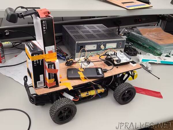
In the attachments section, we have included a plot of the lane-keeping error, the proportional response, and the derivative response versus the frame number; a plot of the error, steering PWM, and speed PWM versus the frame number; and images of our car’s mechanical setup. The camera needed to be placed high enough above the track for the resolution to capture the lane, and the wires and batteries needed to be secured so that the car was stable throughout the duration of the track.”