
“This project replaces the VINCA DTCR-03 “RS232” Digital Caliper Data Transfer Cable with a WiFi enabled ESP8266/ESP32.
The VINCA DCLA-0605 Caliper only supports data transfer to a computer over a proprietary cable.
Decoding the Serial Protocol
The connector is a USB micro, so I cut down a cable and started looking at the lines with an oscilloscope. It was easy to identify that the D+ and D- lines have clock and data. Since it has a clock, that means it’s a synchronous protocol, even though Amazon says it’s RS232. I wrote a Python script to extract the 24 bits being sent at 150ms intervals and record them to a CSV. Then I spent a lot of time trying to understand the data by trying to fit it to all the floating point standards I could find, but nothing worked. Eventually, I got it to work as a fixed point1 with the extra 4 bit for flags. One flag represents units (inch / mm), and the other represents the sign (negative when 1).
Hardware
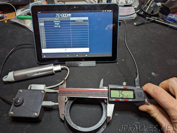
Once I understood the protocol, I was ready to work on the hardware for my solution. I wanted to use the ESP platform so I can send the data over wifi, but the serial data is at 1.2v and the ESP runs at 3.3v. I started looking at level shifters, but most of the online designs are based on the 2N7000 MOSFET, but 1.2v wasn’t enough to trigger the gate. I was looking at MOSFET with lower VGS trigger voltage, but I didn’t want to use a special part. Eventually, I’ve realized I can just use a 2N2222 bi-polar transistor. I’ll lose the MOSFET performance, but it’ll be more than enough for digital 1 and 0 levels.”