
“We are building a device through which we can monitor the usage of electricity of a device and also tell the device to remind us if that app
Overview
A device used to measure the voltage, current, and overall power consumption of an appliance to monitor the regular usage of electricity.
Background
Monitoring the voltage consumption and variations depending upon the appliances to keep track of the overall utilization is a time-consuming and costly process as it involves installing separate devices for each purpose. Using IoT-based equipment we can build a single and more efficient gadget, optimizing the attributes as well.
All the more, it has a wide range of applications and diverse practical use stretching from a household management criterion to the basic building block of a much larger industrial project.
Specification
This specially designed power meter can be attached externally to any appliance with no extra effort and hardware required.
Description and Procedure
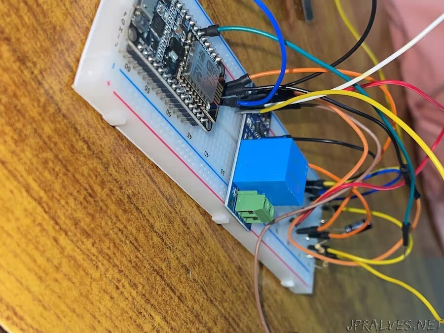
The wiring schematic is straightforward. SCT-013 Current Sensor and ZMPT101B Voltage Sensor VCC are both linked to ESP8266’s Vin, which is a 5V supply. Both modules’ GND pins are wired to the ESP8266’s GND. The GPIO35 of the ESP8266 is connected to the ZMPT101B Voltage Sensor’s output analogue pin. Similar to this, the GPIO34 of the ESP8266 is connected to the output analogue pin of the SCT-013 Current Sensor. A 10uF Capacitor, two 10K resistors, and a single 100 ohm resistor must be connected.
The input AC Terminal of the Voltage Sensor is connected to the AC wires where the current and voltage needs to be monitored in addition to the circuit portion. Similar to the above circuit, the current sensor clip has no connections, and a single live or neutral wire is put inside the clip portion.
Optional requirement
It’s not necessary to utilize a 16x2 LCD in this project. As we will be watching the ESP8266/ power Meter Data on the Application, there is no need to connect the LCD. There are numerous connections required if you want to connect the LCD. Connect the ESP32 D13, D12, D14, D27, D26, and D25 pins to the LCD’s pins 4, 6, 11, 12, 13, and 14. Connect the LCDs 1, 5, 16, and 2, 15 pins to GND and 5V VCC, respectively. To modify the LCD Contrast, attach a 10K potentiometer to Pin 3 of the LCD.”