
“This is a small graphics library, specifically aimed at ATtiny microcontrollers, for the variety of small colour TFT displays available at low cost from suppliers like Adafruit, AliExpress, or Banggood.
It’s an updated version of my Tiny TFT Graphics Library. This latest version of the library supports both the classic ATtiny processors, such as the ATtiny85, and the new 0-series, 1-series, and 2-series ATtiny processors, such as the ATtiny402. Like the original library it allows you to plot points, draw lines, draw filled rectangles, and plot characters and text with an optional scale factor, in 16-bit colour.
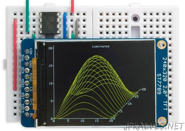
This version adds the ability to plot outline rectanges, and outline and filled circles. I’ve included demo curve-plotting and histogram-plotting programs that adjust to fit any display.
Introduction
This library supports TFT displays that use an SPI interface and require four pins to drive the display. This leaves one pin free on an 8-pin chip such as the ATtiny85 or ATtiny402. If you need more pins choose a larger chip, such as the ATtiny84 or ATtiny404.
Unlike my Compact TFT Graphics Library which uses standard Arduino SPI calls, this library uses direct I/O pin manipulations. This means that you can use any assignment of pins to the four I/O lines needed by the display, and makes it about twice as fast as one using SPI calls. I’ve also added support for some additional displays, so it now supports 16 different TFT displays.
How it works
On the classic ATtiny processors, such as the ATtiny85, the library uses the feature that you can toggle one or more bits in a port by writing to the PINB register; for example, to enable or disable the chip-select signal:
PINB = 1<<cs;
So provided you set all the pins to their disabled state at startup, the display routines can simply toggle the appropriate pins to enable or disable them.
On the new ATtiny 0-series and 1-series processors the equivalent OUTTGL register is used; for example:
PORTA.OUTTGL = 1<<cs;
The differences between each family of processors are handled by constants to define the pin assignments, and preprocessor macros to define the bit manipulations. If you use the circuits given below you won’t need to change anything, apart from specifying which display you’re using.
The ClearDisplay() routine has been optimised further by realising that we don’t need to keep setting the mosi bit, since to clear the display it is always zero, so the routine only needs to toggle the sck bit the appropriate number of times. I’m grateful to Thomas Scherer for suggesting this.”