
“1 Watt FM Transmitter amplifier with a reasonably balanced design specified to boost a RF frequency in the 88 – 108 MHz spectrum. It may be considered a fairly sensitive configuration when used with quality RF power amplifier transistors, trimmers and inductors. It involves a power amplification factor of 9 to 12 dB (9 to 15 times). At an input power of 0.1W the output may be well over 1W. It’s advisable to choose T1 transistor on the basis of the input voltage. For 12V voltage it is recommended to use transistors such as 2N4427, KT920A, KT934A, KT904, BLX65, 2SC1970, BLY87. For 18-24V voltage may may want to use transistors such as 2N3866, 2N3553, KT922A, BLY91, BLX92A. You may also consider using 2N2219 with 12V input voltage however that would only produce an output power of around 0.4W.
How to Calibrate 1 Watt FM Transmitter Power Amplifier
Initially don’t apply any sort of RF input, simply use the power and check with a meter the voltage at point 1. Calibrate R3 as you get the reading near about 0.7V. Use the antenna with a 2 x 100 Ohm 0.5W resistors in parallel at the RF output. After this attach the rf source that may be supposed to boost and link up this RF input to the output.
Carefully set up C1 so as to extract the most optimal potential magnitude on the rf link. Next up, rotate R3 once more to acquire 0.7 V at point 1. Finally set up C5 and C6 for ensuring the highest output voltage (quite between 12V to 18V).
Verify the dissipation of T1’s heatsink, if you see it to be just fine switch off the power, isolate and pull of the 2 resistors of 100 Ohm and connect back the antenna (make sure the the probe stays connected). Connect again the power and yet again allign C1, C5 and C6 for highest voltage read on the probe.
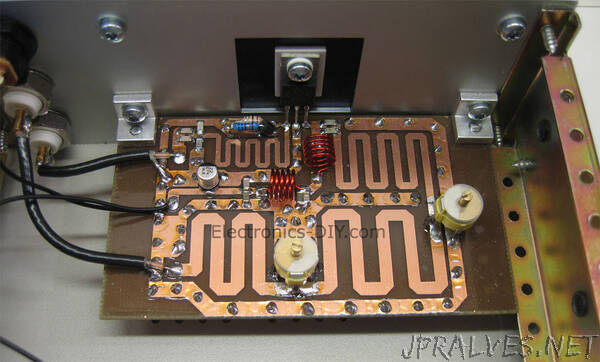
You could think of using a an ammeter for enabling reading the current incourse via T1. This must be restricted below 150mA at 12V and 100mA at 24V otherwise the transistor may well fry of. L2 and L3 coils must be installed at an angle of 90 degrees between the two.
Component List
R1 = 100 Ohm
R2 = 2.2K for 12 V and 4.7K for 24 V
R3 = 10K
R4 = 100 Ohm
C1 = C5 = C6 = 10 – 60 pF
C2 = C4 = 1 nF
C3 = 10 uF
D1 = 1N4148
L1 = 20 turns of 0.2mm super enameled wire over R4
L2 = 7 turns of 0.8mm super enameled wire with 6mm diameter on air
L3 = 4 turns of 0.8mm super enameled wire with 7mm diameter on air
T1 = 2N4427, KT920A, KT934A, KT904, BLX65, 2SC1970, BLY87 (2N2219, output of 0.4W) at 12V
T1 = 2N3866, 2N3553, KT922A, BLY91, BLX92A at 24V”