
“If you have an oscilloscope, you don’t need to buy a V-I Component Tester. Development based on v0.
This is a development of it by using transformers and relays. On this project I used 3V telecommunication relays. Particularly I would like to note that you cannot drive relay coils directly from Arduino or similar microcontrollers’ I/O channels, it directly burns out your controller.
Instead, as already done on this implementation;
Determine the impedance of relay coil by a multimeter (my relays’ coils have typically 44 ohm impedance)
Determine the current range to drive the relays: Acceptable voltage levels of my relays are 2.25-3.90VDC so current range is ~51-88 mA.
Use a transistor to drive coils by current. That’s why on my implementation I could use directly 12VDC since transistors determine the collector current.
Keypad: Since almost all digital channels of Arduino Nano are used to control relays, I decided to use an analog input for keypad. Keypad itself is powered directly by Arduino Nano’s 3.3V output and each key returns a different voltage level. When key reading function is called, few readings are executed on AI, then averaged to ensure the correct reading.
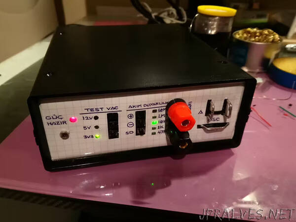
LED Indicators: Except the Power Indicator, all LED’s are directly controlled by circuit itself. Power Indicator has 2 functions in fact: If it’s blinking, system is at “test mode” (at startup). Except that, it illuminates steady.
Jumpers: Jumper_3V3 jumpers are to be closed for operating respective section by 3.3VDC. Generally all circuits are designed for 5VDC level operations.
Power Supplies: A 12VDC transformer is used for AC voltage source for VI Signature Tracing. The second transformer has 2 ea 9VAC coils. One of them is configured for ~12VDC supply to relays while the second is configured for ~10VDC to Arduino Nano. By the way, entire system is able to accept directly line voltage at single point.
TestProbeConnections: Female banana connectors are used so standard multimeter probes can be connected to them.
Oscilloscope Connections: To connect oscilloscope probes, I just formed 1.5 mm2 solid cable cores.
Software: Software just continuously reads the keypad, and take defined actions if a key is pressed. At startup, power indicator blinks then turns off. Upon that system activates and deactivates relays corresponding to Test Voltage Levels 3.3V, 5V, 12V and then Current Sensing Resistors 47R, 1K, 10K, 1M, 10M. Then system gets itself back to 3.3V / 47R and switches Power Indicator on (steady).
Modular Structure: As you can notice on photos and circuit schematics, I made the entire design as a modular structure by different boards, so it can be disintegrated as needed.
Continuous Current Sensitivity Switching (CCS): It’s a specific function designed and coded particularly continuous switching forward and backward through 47R-1K-10K-1M-10M current sensing resistors. During this mode, it’s also possible to adjust test voltage levels.”