
“How to use the Arduino with a X9C104 pot to implement a pseudo Phase Locked Loop square wave generator
This project shows how to use the Arduino with a X9C104 to implement a frequency generator such that the frequency is optimized using a feedback loop. This is the principle used in a PLL circuit.
This project shows how a X9C104 IC is controlled by an Arduino and used in a feedback loop with a 555 Timer circuit to output a user required input frequency. This frequency is set close to the input by using a feedback loop connected to an Arduino interrupt.
The basic principle of operation:
- User inputs a required frequency via the Arduino serial monitor.
- Arduino accepts input and programs X9C104 to an initial setting
- X9C104 resistance in 555 timer circuit adjusts frequency of oscillation
- The resulting square wave is fed back into the Arduino interrupt (pin 2)
- Using an interrupt handling routine, the frequency of the square wave is determined
- This frequency is compared with the required and adjustments are made to X9C104
- Frequency is measured again and a second optimization is performed
- Frequency of output square wave from 555 timer settles to value set by user in step 1
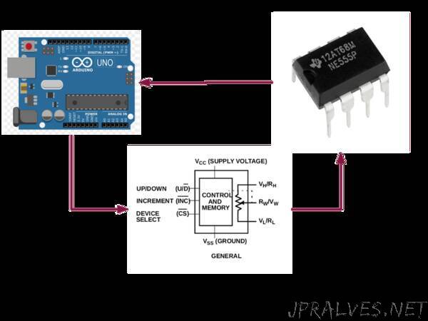
X9CXXX Digitally Controlled Potentiometer (XDCP)
The X9CXXX integrated circuits are manufactured by Intersil (recently acquired by Renesas Corporation) and represent their range of digitally controlled potentiometers. The device includes a resistor array, control section and non-volatile memory. The resistance of the array is controlled by a three wire digital interface.
The device can be used as two terminal variable resistor or a three terminal potentiomenter. It includes non-volatile memory that holds the last resistance value on power down and sets the resistor array to this value on subsequent power up.
Control of the wiper position and hence the resistance is determined by the three digital inputs:
- Device is selected by taking CS low.
- State of Up/Down (U/D )determines whether the wiper moves closer to Vh/Rh or Vl/Rl.
- The wiper moves one step every time INC is taken low and then returned to high.
- The wiper has 100 possible positions (0 – 99), allowing for incremental steps of 1% of the total resistance.
- When the wiper reaches the top or bottom ( Vh/Rh or Vl/Rl), it does not move any further nor does it wrap around to the other extreme.
It is important to remember that the wiper moves a single increment for each INC cycle. The wiper cannot jump across multiple steps. This means that moving from step 10 to step 20 requires 10 INCcycles.
Vh and Vl cannot exceed Vcc and Vss.
Complete specifications for the devices can be found at the Renesas website.”