
“Self-learning UHF receiver consisting of a radio receiver board with Motorola decoding and a module equipped with 8 relays operating in impulse or bistable mode.
In many home automation applications and in general where it is necessary to exercise remote control by radio of multiple devices installed in the same place, the classic single and dual-channel handheld transmitters are not particularly practical, because using common radio controls (TX/RX) should be installed more than one receiver, with an obvious increase in cost, space and complexity, since each receiver unit has redundant parts that could be pooled: for example the RF receiver. This is why it would be useful to have a single radio control system and, in particular, a receiver unit that supports all the channels required by the system; an example is a receiver described in these pages, which allows the remote management, via AM radio links at 433.92 MHz, of 8 users manageable with the clean contact of one relay each. It is, therefore, a radio control system in which we can combine a receiver with eight outputs, a single eight-channel transmitter, two four-channel, four two-channel, or eight single-channel transmitters, or combinations of them because the beauty of the receiver is that it learns the code regardless of which transmitter it comes from.
Thanks to a suitable relay interface, the receiver can switch users either operating at low DC voltage or at 230Vac mains voltage, which absorbs up to 10 amps each.
The coding used is the Motorola MC14502x standard, so it allows a maximum of 19,683 combinations for each channel unless you use multi-channel TX; in fact, in this case, the combinations must be divided by the total number of channels, but this limit is not derived from the receiver (which, as we will see, treats each code individually, regardless of the type of transmitter that generates it) but rather from the encoder of the transmitter.
As it works, our receiver, compared to a traditional device, allows us to better exploit the encoding: in fact, if we had a single decoder onboard, such as the MC145028 for example, decoding 8 channels would mean allocating the last two three-state bits to the definition of the channels and leaving the remaining 7 to the actual encoding of the transmission; instead in the receiver we propose the decoding is managed by a microcontroller and each channel is treated independently from the others, i.e. the code that the relative TX transmits is memorized separately.
So here we could combine eight Motorola MC14502x single-channel encoded transmitters, each of which can be set by choosing from 19,683 combinations! This is the main advantage of our system, which allows maintaining high security against burglary while using coding that, if you like, can be considered outdated and not very effective in front of the most advanced rolling-codes.
The learning is done individually for each channel, which opens the way to many possibilities of use, as we can combine each output relay with a single-channel TX or a two-channel channel. The firmware of the microcontroller that controls the receiver makes sure that a remote control cannot control multiple relays.
But let’s leave this reasoning aside and let’s go immediately to see what it is about, analyzing the system, which is composed of a receiver unit described in these pages and a handheld transmitter that you can already buy and that therefore goes beyond this discussion.
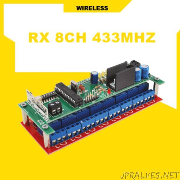
The receiving unit is in turn composed of a printed circuit to be self-built and of which in the next paragraphs we describe the wiring diagram, as well as a relay power actuator board, which is a finished product that can be purchased in our store with the code 2846-RELAY8CH. The circuit to be built is the Motorola radio receiver and decoder block, in which we have integrated also the power supply stage for the whole set.
CIRCUIT DIAGRAM
Let’s focus now on the circuit, better described by the wiring diagram you can find in these pages, which is based on a hybrid receiver module as RF section and on a Microchip PIC16F876A-I/SP microcontroller as a Motorola MC14502x standard decoder and output status manager. All this is completed by a voltage regulator that allows to obtain the 5 volts to operate the logic on board and the external relay board.
The radio receiver module is an AC-RX2/CS hybrid integrated circuit produced by Aurel, equipped with a front-end with 50-ohm antenna impedance, input amplifier and super-regenerative tuning stage with low spurious emissions (-65 dB), characterized by high sensitivity (-100 dBm) and discreet selectivity (the bandwidth at -3dB is 2 MHz) ensured by a ceramic filter; inside this hybrid, downstream of the tuning stage is the OOK (On-Off Keying) amplitude demodulator which provides pin 13 with the demodulated signal as it is and pin 14 with the demodulated signal but squared by a comparator based on the integrated LM358, which allows reconstructing the pulses transmitted by the handheld TX with the up and down fronts well squared, as required by the microcontroller of the circuit to ensure effective decoding.
The micro U2 receives at pin 7 (I/O RA5 configured as input without pull-up) the signal provided by pin 14 of the hybrid U3 and decodes it thanks to a special routine, which is started by the main program when, running in a loop, it verifies a level transition in the incoming signal, i.e. the start bit of the data sending.”