
“We can make the lighting switches in our house smarter with this ESP8266 circuit, so if no WiFi it will continue to work as a normal switch.
We can make the lighting switches in our house smarter with this ESP8266 circuit, so if something goes wrong (e.g. if there is no WiFi or the server is down) it will continue to work as a normal switch.
You can find the original writing here: Smart Alternative Switch with ESP8266 for ioBroker via MQTT
Attention!
Parts of the following circuit work with Mains voltage. Mains voltage is not a toy, it can cause fatal electric shock or fire! Only at your own risk and only if you know what you are doing!
The area marked in red in the following figure is below Mains voltage!
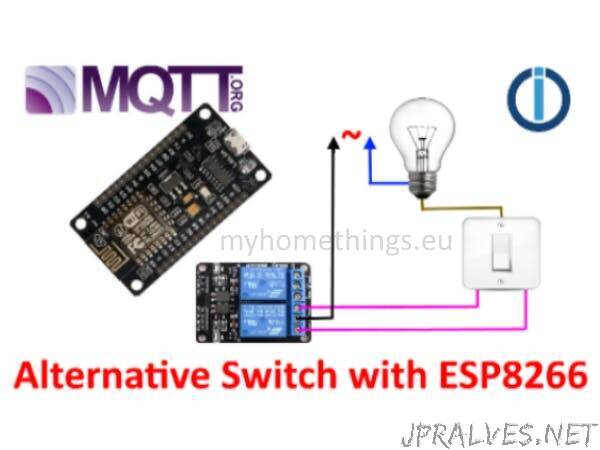
Let’s see the circuit. I tried to draw intelligibly, I hope it worked.
I use this circuit in the European Union, where the mains voltage is 230V! If you want to use it and the mains voltage in your area is not 230V, you could do so by replacing the power supplies shown in the illustration.
In addition to the normal alternative switch, the relay module must be installed as if it were another alternative switch. This relay module has an optocoupler so that the ESP8266 microcontroller is completely optically isolated.
In the figure, the upper black cube is a switching power supply with 230 V to 3.3 V (If the mains voltage is not 230 volts, it must be replaced! ). Its 230 V input is connected to the lamp, its output is routed to the ESP8266 D2 pin via an optocoupler (pc817). This is used to monitor whether the lamp is lit or not. Input D2 must be switched to 3.3 V with a pull-up resistor.
The lower black cube is a 230 V to 5 V (If the mains voltage was not 230, this must also be replaced!) switch mode power supply that supplies power to the low voltage part of the circuit.”