
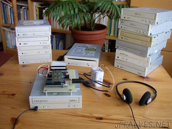
“This project makes the Arduino work as a simple ATAPI controller for a CD-ROM drive. It implements the following functions: PLAY, PAUSE, RESUME, NEXT, PREV and EJECT/LOAD.
It has no own display -yet- but when connected to a PC the Arduino will communicate via the ‘Serial.print’ function the progress of CD-ROM initialisation and echo the operations started when a push button is pressed to command the CD-ROM. Also basic current track infromation is displayed. I found that not all CD-ROM drives react the same to ATAPI commands and that they differ also in their response speed.
The sketch was tested alright with the following drives:
LITE-ON LTN-403L 2000
Aztech CDA 668-01l 1995
LITE-ON LTN-486S 2001
LG CRD-8320B 1998
LG CRD-8521B 2001
CREATIVE CD5233E
Hitachi CDR-8130 1997
SONY CDU5211 2001
Following CD-ROM/ DVD drives did not work:
LG CRD-8322B
Goldstar CRD-8240B/8241B
Samsung DVD master 8E SD-608
Toshiba XM-6702B
Plextor PX-W2410TA
The LG CRD-8521B is a bit special, it will get stuck if no CD is placed in the tray before it initialises. Even the drive’s own eject button will not respond. To overcome this situation keep the drive’s eject button pressed while resetting the Arduino. This will open the tray and a CD may be inserted. Besides this it works fine and supplies my headphones while typing this lines.The Arduino interfaces to the IDE connector of the ATAPI drive via three PCF8574 I/O expanders which provide the necessary 24 I/O pins. Each PCF8574 I/O expander interfaces to a part of the IDE signals. The expanders have the addresses 20, 21 and 22 (hex).
Addresses 20h/21h interface to the lower/upper 8 bits of the data BUS (DD0-DD15).
Address 22h combines the addressing of the ATAPI register set, the read and write strobe signals and the hardware reset pin of the IDE.>The schematic of the IDE interface is basically the same as the one presented in example 21.1 of John Boxall’s great introduction to Arduino and I2C.
For a test I did connect the 24 LEDs to the outputs of the PCFs and ran the script provided by John for the example. Later the LEDs were replaced by pull-up 4K7 resistors. These are not reflected in the schematic and as far as I could experience they are not necessary, at least not with 4 inches long 40 pin IDE cable.
Connection to Arduino is simple, the I2C signals SDA/SCL from the IDE controller interface connect to Arduino pins 4 and 5.
Aditionally ground and +5V from Arduino are needed as well, that’s it.
On the Arduino some push buttons are required. These are wired so that when operated the corresponding Arduino pin (8 to 12) is connected to ground triggering the desired function.
Taking it into Operation
Connect the IDE cable to the CD-ROM drive, make sure the jumper at the rear of the CD-ROM drive is set to select it as master. Power up the Arduino first and then the CD-ROM drive. Of course, the CD-ROM drive needs its own power supply!
It is recommended to have a CD in the tray at the beginning. First time connect the Arduino also to the PC, download the sketch and open the serial interface.
In case the sketch is already on the Arduino do the same but reset Arduino after powering the CD-ROM.
Whenever the Arduino reset button is pressed, a consequent hardware reset is issued to the ATAPI interface too. This is acomplished by shortly setting port 5 of the I/O expander (Addr.22h) to ground. The attached drive should (regardless of being or not a compatible one) react with the same characteristic noise as when it is first powered on. This is a good but not exhaustive test that proves Arduino is communicating with the I/O expander and that a least the wiring to the nRST pin on the IDE ATAPI interface is correct. Should this not be the case revise the wiring.”