
“Few months ago, a friend of mine gave me a couple of discarded inkjet printers and copy machines. I was interested in harvesting their power source units, cables, sensors and especially motors. I salvaged what I could and I wanted to test all the parts to make sure they were functional. Some motors were rated at 12V, some at 5V, some were stepper and others were DC motors. If only I had a device, where I could simply connect the motor, set the frequency, duty cycle and select a stepping method to test it.
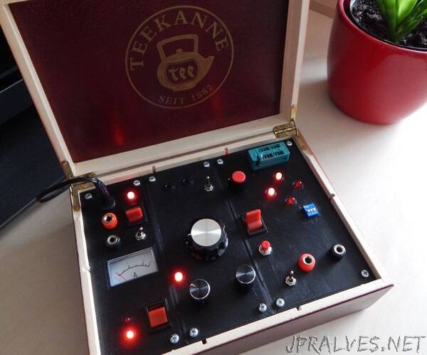
I decided to build it without using digital signal processor, or microcontroller. The humble 555 or tl741 as oscillator, 4017 counter and many logic gates for stepper motor modes. At first I had lot of fun designing the circuit, as well as designing the front panel for the device. I have found a decent wooden tea box to put everything inside. I have divided the circuitry into four parts and started testing it on a breadboard. Soon, the first signs of frustration appeared. It was a mess. Lot of gates, lot of ICs, wires. It didn’t work properly and I was thinking between two options: To make it very simple - just for DC motors, or put it aside and finish it sometimes later … I choosed the second option.”