
“The LM350 is a tried and true 3A adjustable voltage regulator. It accepts an input voltage up to 35V and can deliver an output voltage between 1.25 and 33V. It is rugged beyond belief. Where fairly beefy step-down converters go up in smoke, the LM350 just takes a nap. And a nap is infinitely better than a plume of smoke. LM350 can also be used to limit current though that requires a separate LM350/LM317 in series with our voltage regulator.
I needed a very low-noise variable power supply for some irrelevant project, and having tested a handful of step-down converters on an oscilloscope, I really was annoyed. They are nice, but they are noisy. This circuit required as little noise as possible, and to compound my irritation, my modified desk PSU was doubly noisy. The M317 has an absolute maximum current limit of 1.5A, which was too little for my project, so I got a LM350, and was instantly satisfied.
The LM350 accepts an input voltage up to 35V, can output 3A, and can deliver an output voltage of between 1.25 and 33V. It will enter a temporary coma if overheated, and really requires serious abuse before it dies. As a voltage regulator of the old school, it does require some heatsinking, but heatsinks are cheap. For this variable voltage regulator, a heatsink that can dissipate 5 watts is used. It is best to keep the input voltage as close to the output voltage as possible, since the formula: ‘P_dissipate = ( Vin – Vout ) * Iload’ tells us that for e.g. (12V – 5V) * 0.5A = 3.5 watts must be dissipated. And that’s for the standard effect of a USB2.0 port, regulated down from 12V. For P_dissipate = ( 6.5V – 5V ) * 0.5 we get 0.75 watts, a more reasonable amount of wasted energy turned into heat, and that will easily be dissipated. The formula for calculating voltage output is:
Vout = 1.25 * ( 1 + ( 150 / ( R1+10 ) ) = ?V
Notice that there is a 10 ohm resistor in series with the trimpot, yielding a minimum output voltage of 1.33V.
The pinout of the LM350T is pin 1: Adj(ust), pin 2: Vout, pin 3: Vin. While I have seen perfectly clean power output on a LM350 under load, we will add some capacitors to trim the input and output. These soak up noise, and though not strictly necessary, every little bit helps. We use a 0.33uF capacitor on Vin (C1), and an electrolytic (polarized) capacitor with a value of 1uF on Vout (C2) to improve transient response. The LM350 much enjoys a 150 ohm resistor (R1) between Adj and Vout. For R2 we use a 10 ohm resistor in series with a 10K ohm trimpot to gain variable output voltage. You can use the lm317_calc.py script from our 12V battery charge controller article. Here we do NOT use any protection diodes, but if you plan on using an output voltage greater than or equal to 25V, you should definitely include them.
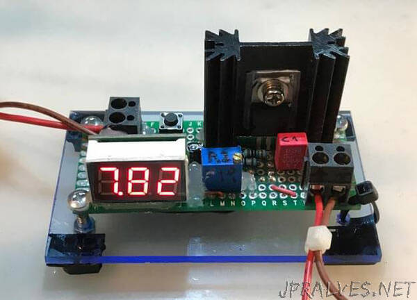
For added convenience, a digital voltmeter is added, but since it does cause spikes in the output current (a few millivolts), it is OFF until you press the little button by the input terminals. It is easy enough to adjust the little trimpot whilst holding down that button. If at any time you need to know the output voltage, just press it again. The one used here was a bit off, by plus 0.12V. Unless it’s an expensive LED voltmeter, it seems this is very common. You may want to consider an analogue voltmeter if you want to avoid noise and have a permanent display of output voltage.
Components Required
1 x LM350T variable voltage regulator (TO-220 package)
1 x heatsink of arbitrary size (38x34x12.8mm TO-220 finned heatsink)
1 x TO-220 insulating thermal pad + plastic sheath
1 x 3mm nut + bolt
A drop of thermal paste
1 x LED voltmeter (optional)
1 x momentary pushbutton (optional)
2 x 2 port screw terminal
1 x 50x70mm perfboard
1 x 150 ohm resistor for R1
1 x 10 ohm resistor for R2.1 (in series with R2.2, min. output => 1.33V)
1 x 5-10 kilo-ohm trimpot for R2.2
1 x 0.33uF capacitor (50V) for C1
1 x 1uF electrolytic capacitor (50V) for C2
Follow the schematic, and don’t be shy. The LM350T can endure 300 degrees celsius for up to 10 seconds, and that tastes like freedom. Pay attention to a proper electric insulation between the heatsink and the LM350T. Test continuity from the tab to the heatsink after you’ve mounted it. If you have no continuity test on your multimeter, use the 200 ohms setting. Of course, if you don’t mind having Vout on the tab as well as pin 2, you can skip this step.
You may have noticed the splodges of silicone glue on the example board. There is a reason for that – particularly trimpots and capacitors don’t handle being moved ever so slightly over longer periods of time. Your solder joints may be solid, but even this malleable metal from which the pins are made will eventually succumb to metal fatigue. When they break, you’ll have to fix it. This board lives in my special Box of Many Things, and I will regularly jostle that box around, rummage through it, and so forth. By applying a few unsightly blobs of glue you can be certain that nothing falls apart. The higher the temperature, the better the bonding!
If you’ve followed the schematic, you now have a very nice little power supply. I retired my puny buck-boost supply after I started using this one. The device would benefit from a larger heatsink, but this is not something intended for permanent installation somewhere – at most, I’ll pull 500-750mA of continuous current. And remember: the output current is so squeaky clean it can even be used for RF applications. If you’ve got a circuit that’s misbehaving, and you suspect the culprit is noise, try using this to supply power – particularly the HopeRF 433/868MHz and longer range LoRa SX1278 radio modules will benefit greatly.”