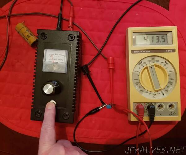
“This tester can be used to check smaller value capacitors to see if they have leakage at their rated voltages. It can also be used to test insulation resistance in wires or to test a diode’s reverse breakdown characteristics. The analog meter on the front of the device gives an indication of the current going through the device under test DUT and the multimeter gives the voltage across the DUT.
NOTE OF CAUTION:
THIS DEVICE DEVELOPS VOLTAGES UP TO 1000 VOLTS WHICH CAN BE LETHAL IF THIS DEVICE IS MISUSED. ONLY BUILD THIS DEVICE IF YOU UNDERSTAND THE SAFETY PRECAUTIONS FOR WORKING WITH HIGH VOLTAGES.
Supplies:
All the pieces used here I had on hand and most came from salvaged parts from other devices or bits and pieces I acquired long ago. If you want to make the project yourself, here are the tools and parts you will need:
Tools:
1) Pliers: Long nosed,
2) Soldering Iron 40 watts
3) Electronics solder
4) Electric drill with drill index.
5) Reamer and miniature file set
6) Multimeter
7) Assorted screwdrivers
Parts:
1) (2) 2N3904 bipolar transistors
2) (2) 1k resistors
3) (2) 4.7k resistors
4) (3) 15 nF capacitors
5) (2) 1N914 diodes
6) (1) IRF630 MOSFET
7) (1) 10-1 miniature audio transformer
8) (1) miniature single pole single throw pushbutton switch (normally off)
9) (1) 1/2 watt, 1 megohm potentiometer
10) (1) 9 volt battery connector
11) (1) 9 volt battery
12) (13) 2000 pF capacitors rated at least 400 volts.
13) (13) 1N4007 diodes
14) (1) set of banana jacks, one red one black.
15) (1) miniature analog meter for current indication. Preferably less than a 1 milliamp movement.
16) different colors of hookup wire and heat shrink tubing to fit over wires that carry high voltage.
17) knob for potentiometer”
