
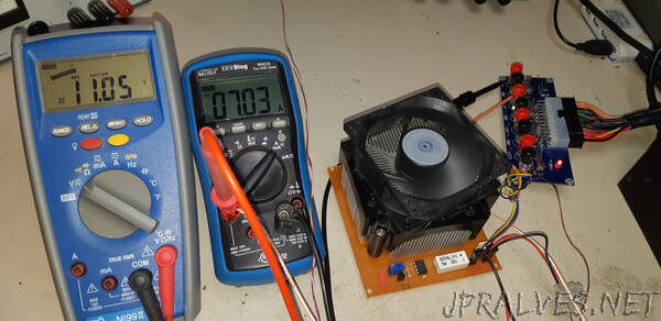
“I wanted to test a pc power supply
At first I was messing about with some big resistors but then I decided it would be nice to have an “active load” that you can set to a particular current. You can buy these things for quite some money but I decided to design and build myself a simple one using components and tools I have lying around. I decided to go analog, no digital stuff this time. Commercial loads can have different modes such as constant current, constant voltage, constant resistance and constant power, but mine will only have constant current.
Specifications
- Constant current only
- Current settable between 0A and 10A
- Maximum power 120W
- Maximum voltage 200V
- Power supply 12V
Bill of materials
- IRFP250 MOSFET
- LM358 opamp
- TL431A voltage reference (or zener diode 2.5V)
- 100nF capacitor
- 20k trimmer resistor, 10 turns (lin or log)
- 0.1 Ω, 10W shunt resistor, cement
- 1kΩ resistor
- pcb size 10 × 11 cm
- a salvaged aluminium cpu cooler with 12V fan
- 4 pin header
- 2 pin header (×2)
Theory of operation
The IRFP250 MOSFET that I use, will dissipate most of the power. It can dissipate a maximum power of 190W (under ideal circumstances, but not in real life). It will heat up to, say, 75 °C and at that temperature, the maximum power it can dissipate is still 115W. It is therefore of great importance to keep the MOSFET cool, because the higher the temperature, the lower the allowable power. Therefore, we will use a salvaged pc cooler, which is a big chunk of aluminium with lots of cooling fins and a fan to keep it cool. Open up that unused pc in the attic and remove its cpu cooler!
Together with an opamp, the LM358, it forms a current sink that can be set at a constant current based on negative feedback. Refer to the circuit diagram. The TL431A delivers a constant voltage of 2.5V. Ten turn trimmer resistor R3 can put any voltage between 0 and 2.5V on the positive input of the LM358. Lets say it’s set at 1V. The opamp will try to keep the voltage on its negative input equal to the voltage on its positive input. Therefore, the voltage over R1is also 1V. Because the value of R1 is 0.1Ω, the current will be 10A.
How does the opamp keep the current constant? That is because of negative feedback. Let’s say that the current through R1 is a little bit too high. Then, the voltage on the negative input of the opamp will be a little bit higher than the voltage on its positive input. Because the opamp has a high amplicication, the voltage on its output will drop a bit. Therefore, the voltage on the gate of the MOSFET will drop, which makes the MOSFET a little less conductive and therefore the current will decrease.
The LM358 is suitable for single supply, in other words no negative supply is needed, which basically means it accepts inputs as low as 0V and can also output (almost) 0V.”