
“This article, the first in a series on “timer/counter” functions in microcontrollers, discusses periodic timers.
This article is the first in a series on “timer/counter” functions in microcontrollers. The focus is not on a particular family of microcontrollers but describes timer functions in general. I start with looking at features in common with most types of timers. Then, I go into the periodic timer and how it can be used. I describe the SysTick timer in detail as an example. Subsequent articles cover other common timers.
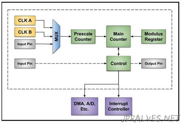
Every timer needs a clock source or timebase. There are often several possible clock sources and one is selected with a switch or multiplexer. Sometimes an external clock source is an option. To increase the count range, the selected clock goes to a “prescaler” which divides the clock before it goes to a main counter. The dividing factor of the prescaler is usually limited to powers of 2. For example, 20 through 27 gives choices of 1, 2, 4, 8, 16, 32, 64, or 128. Some prescalers go up to 216 or 65,536. The output of the prescaler goes to a main counter which is often 16 bits wide and counts within the range of 0 to 65,535. Sometimes two 16-bit counters can be combined to form a 32-bit counter, but most timing functions are possible with a prescaler and a 16-bit main counter. The count range of the main counter is set by a “modulus” value (M) stored in a register. Here is a typical counting sequence with M = 999. This is a down counter which reloads the modulus value on the next clock after it reaches 0.”