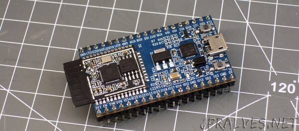
“The ESP32 is a next-generation, WiFi- and Bluetooth-enabled microcontroller. It’s Shanghai-based Espressif’s successor of the very popular—and, for the hobbyist audience, revolutionary—ESP8266 microcontroller.
A behemoth among microcontrollers, the ESP32’s specs include everything but the kitchen sink. It is a system-on-a-chip (SoC) product and practically requires an operating system to make use of all its features.
This ESP32 tutorial will explain and solve a particular problem of sampling the analog-to-digital converter (ADC) from a timer interrupt. We will use the Arduino IDE. Even if it is one of the worst IDEs out there in terms of feature sets, the Arduino IDE is at least easy to set up and use for ESP32 development, and it has the largest collection of libraries for a variety of common hardware modules. However, we will also use many native ESP-IDF APIs instead of Arduino ones, for performance reasons.
ESP32 Audio: Timers and Interrupts
The ESP32 contains four hardware timers, divided into two groups. All timers are the same, having 16-bit prescalers and 64-bit counters. The prescale value is used to limit the hardware clock signal—which comes from an internal 80 MHz clock going into the timer—to every Nth tick. The minimum prescale value is 2, which means interrupts can officially fire at 40 MHz at the most. This is not bad, as it means that at the highest timer resolution, the handler code must execute in at most 6 clock cycles (240 MHz core/40 MHz). Timers have several associated properties:
divider—the frequency prescale value
counter_en—whether the timer’s associated 64-bit counter is enabled (usually true)
counter_dir—whether the counter is incremented or decremented
alarm_en—whether the “alarm”, i.e. the counter’s action, is enabled
auto_reload—whether the counter is reset when the alarm is triggered
Some of the important distinct timer modes are:
The timer is disabled. The hardware is not ticking at all.
The timer is enabled, but the alarm is disabled. The timer hardware is ticking, it is optionally incrementing or decrementing the internal counter, but nothing else is happening.
The timer is enabled and its alarm is also enabled. Like before, but this time some action is performed when the timer counter reaches a particular, configured value: The counter is reset and/or an interrupt is generated.
Timers’ counters can be read by arbitrary code, but in most cases, we are interested in doing something periodically, and this means we will configure the timer hardware to generate an interrupt, and we will write code to handle it.
An interrupt handler function must finish before the next interrupt is generated, which gives us a hard upper limit on how complex the function can get. Generally, an interrupt handler should do the least amount of work it can.
To achieve anything remotely complex, it should instead set a flag which is checked by non-interrupt code. Any kind of I/O more complex than reading or setting a single pin to a single value is often better offloaded to a separate handler.”
