
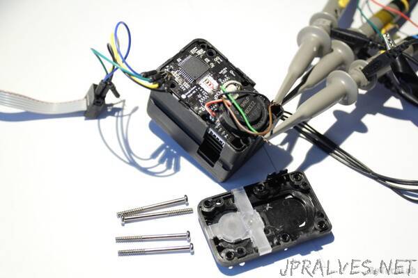
“You must be wondering why I’m “reverse engineering” this servo. The answer is pretty straightforward: someone in my scientific circle has damaged it by connecting the power supply to the wrong pins of the header. As you might have guessed it, the magic smoke has escaped immediately ! .Obviously we could just buy another one, but the main problem with that is: the cost. This servo costs around 320$ + shipping. Upssss , that hurts! Because of that I’ve decided to attempt a repair of it. The next reason why I’ve decided to repair this serwo is that I’ve found that there is a XMega micro controller under the hood (it should be very easy to write a basic code to drive this servo).
UART RX and TX lines are next to the VDD and GND pins which is a bad thing – it is very easy to accidentally swap these and connect VDD to the UART TX or RX lines. That’s why you should always double or triple check what goes where before you power on your expensive device/equipment! . You can also use idiot-proof connectors that can’t be plugged in the wrong way
Due to this mistake the microcontroller as well as the logic level shifting circuit for the UART were burned/ damaged. I’ve started the repair by removing the old uC with hot air gun. Immediately after that I’ve soldered a new one. Of course I’ve tried to download the old firmware form the burned microcontroller, but as you might have guessed it the manufacturer has locked it with lockbits, so I couldn’t do anything with that.
Reverse engineering the PCB:
I guess that the PCB has 4 layers (I’ve noticed some connections that are not directly visible on the top or bottom layer). I finally understood that it will be a pain in the as* to reverse engineer all of the connections with components that are soldered on the PCB. There are many components that are not important from my point of view (bypass caps, pullup/pulldown resistors etc.). I just want to “hack” it and make it work. These are the main reasons why I haven’t made a full schematics of this PCB.
Instead of drawing full schematics I’ll explain where are the most important components , how they are connected to each other and what they do in this circuit.”