
“I found limited documentation on the usage of a color sensor I recently purchased, so here is my attempt to make it more simple.
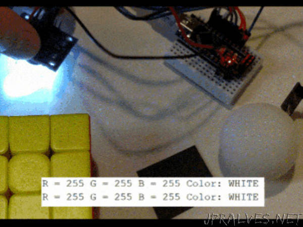
This project uses a TCS230 color sensor I ordered from Amazon. It uses both “passive” and “active” color recognition: Passive recognition goes straight to an RGB LED. Active recognition is processed by the Arduino to output a specific color.
According to a similar product’s datasheet,
In the TCS3200, the light-to-frequency converter reads an 8 × 8 array of photodiodes. Sixteen photodiodes have blue filters, 16 photodiodes have green filters, 16 photodiodes have red filters, and 16 photodiodes are clear with no filters. The four types (colors) of photodiodes are interdigitated to minimize the effect of non-uniformity of incident irradiance. All photodiodes of the same color are connected in parallel. Pins S2 and S3 are used to select which group of photodiodes (red, green, blue, clear) are active.
Materials needed:
Arduino board: https://amzn.to/2DLjxR2
Breadboard: https://amzn.to/2RYqiSK
Jumper wires: https://amzn.to/2Q7kiKc
Color sensor: https://amzn.to/2SfaFXr
RGB LED (common anode): https://amzn.to/2RaP7hE”