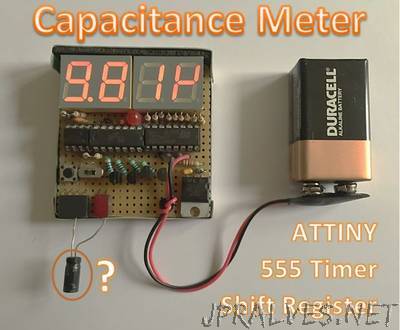
“Capacitors are vital components in electronics, but sometimes they are broken, or the value printed on the cap has become unreadable. Because my multi-meter does not have a capacitance measurement, I decided to make one! The principle of measuring capacitance is quite simple. The voltage of a capacitor charging through a resistor increases with time T. The time it takes to reach a certain voltage, is related to the values of the resistor and capacitor. In this project, we’ll use a 555 timer circuit as a monostable multivibrator. If that sounds like some dark magic to you, don’t worry, it’s quite straightforward. I’ll refer to the the Wikipedia page for the details, as we’ll focus on the things we really need: the schematic and formula. The time in which the capacitor C charges through the resistor R is given by: T = ln(3) x R x C = 1.1 RC. If we know the value of the resistor and the time, we can calculate the capacitance: C = T / 1.1R.”
