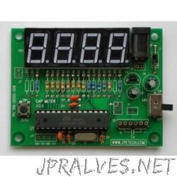
Other
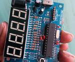
“A capacitance meter is a piece of electronic test equipment used to measure capacitance, mainly of discrete capacitors. Every electronics hobbyist & engineer must have capacitance meter. A capacitance meter is not very cheap one. In this instructables I will show …
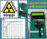
“Hello! For this physics-unit you need: a power supply with 0-12V_ _ one or more capacitors one or more charging resistors_ _ a stopwatch a multimeter for voltage measurement_ _ an arduino nano a 16x2 IC display_ _ 1 / 4W …
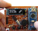
“Hello, this is a mine multyfunctional Arduino device. It can be used to test sensors that are connected to analog pins, to measure resistance, to measure the voltage drop of the diode. It can measure ambient temperature, it has built …
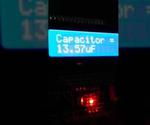
“This project is pratically three components because it’s formed of a 16X2 LCD Display, a potentiometer 10K, and an Arduino Nano. The rest of parts are a PCB 5cm x 7cm, 1 X 40 HEADER, 0.1” SPACING, and …

“Many multi meters (like mine) don’t have the functionality of measuring capacitance. This is especially annoying as one has no way of determining how accurate a capacitor is. If you doubt your resistor you can easily measure it, but …
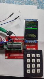
“The talking multimeter uses the PIC32MX250F128B as a voltmeter, ohmeter, and capacitance meter that speaks the reading as it is measured. Spoken measurements improve the usability of measurement devices since the user will be able to focus on the circuit …
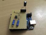
“This tool is used to test capacitors. It is really easy to make, as only additional hardware needed (besides the capacitor that will be tested) is 2x220ohm resistors.”
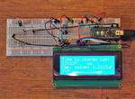
“If, like myself, you’ve got an enormous stash of unlabelled electronic components that seem to look like capacitors, it’s probably a good idea to either throw them away or test them with a capacitance tester. Furthermore, there’s …
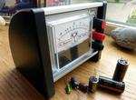
” I finally got round to making my capacitor ESR tester this week after finding a nice simple 5 transistor version by EEVBlog member Jay_Diddy_B. Unfortunately, for me, the design was only SMD so, I decided to replicate his schematic in …
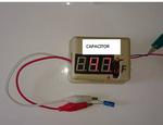
“If you have learned about the capacitor(RF CIRCUIT). the H bridge seem too complex, too many to adjust, too many to change and too many to read for just balancing the bridge ! (not include S.G and CALCULATES yet …

