
“A plethysmogram is a graph of blood volume vs time and a photoplethysmogram (PPG) uses light to measure blood volume, often with a finger probe.
You can buy a pulse oximeter very cheaply on eBay. It uses photoplethysmography to measure your heart-rate. By comparing the absorption of IR versus red light, it can also measure blood oxygen saturation. It’s straightforward to build a PPG that measures red and IR absorption but calibrating it is a problem. The PPG described here only uses IR light.
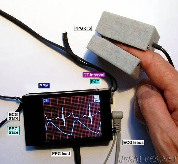
This project is an add-on to my ECG project - I’m going to assume you’ve already built the ECG hardware. The additional hardware and software described here displays a photoplethysmogram next to the ECG trace. A probe clips on your finger and passes infra-red light through it. The amount of IR received is a measure of the blood volume in your finger.
There are two circuits you can use to collect the PPG data:
- build your own amplifier
- use an AD8232 module
Building your own amplifier is slightly cheaper and you probably already have all of the components. An AD8232 module is less work but you have to wait for it to be delivered.
To build the original ECG project, you will need an Arduino Nano, an ILI9341 320x240 SPI display, an AD8232 module, a battery of some sort, a pushbutton and some resistors.
I’ve included a design for a 3D printed PPG clip or you can use a piece of PVC plumbing pipe.
The new software includes code to calculate the QT-interval of the ECG signal. If you have built my ECG project, you can upgrade that project to display the QT-interval. (See the “Analysis” Step below.) You don’t need to build PPG hardware.
This is not a medical device, it’s something you’re building for fun. See the full disclaimer in Step 2 of my ECG project.”