
“Utilizing only the cheap components required for regular sensor functionality, this ATtiny212-based design adds two-way wireless communication for tweaking and reporting of its own parameters. Here’s how it came to be.
Background
A client’s project used a certain off-the-shelf IR proximity sensor module. That module reached its market End Of Life and we needed a drop-in replacement; and while at it, we wanted to address an old pain and have the ability to adjust the sensor’s sensitivity.
The working principle of the sensor is simple: there’s an IR LED which shines constantly, and a phototransistor. When an object is close enough to the module to reflect some of the IR light, it is detected by the phototransistor and translated into an analog voltage. If that voltage is beyond a certain threshold (as determined by a microcontroller or some comparator circuit), a digital signal appears on the output pin.
Creating a basic circuit to do the above is easy enough. With the addition of a trim potentiometer, we can make the threshold adjustable – but not easily replicable. That is to say, if I want to replicate the settings of a specific module, it’s going to take a lot of uncomfortable voltmeter and screwdriver work. What we really want is to be able to read and set the value digitally, while keeping the BOM short and cheap.
First attempt
I designed a sensor module based on the OPB732 “Long distance reflective switch”, which was both relatively cheap and available, and on the ATtiny202 8-pin microcontroller.
The ‘202 has the ubiquitous ADC peripheral, so it could measure the phototransistor’s output with minimal external components. All that remained was the matter of communication. For that, I added three SMD pads at the edge of the board: Ground, TX and RX (from the ATtiny202’s USART peripheral ). I even designed and 3D-printed a little tool to help me hold three jumper wire tips against those pads for convenient “programming”.
This setup worked; using a USB-to-UART adapter, a couple of wires and a simple terminal software on the PC, My client and I were able to set the threshold value for the module, and to read it back. However, the process were still clumsy and uncomfortable, especially after the module was soldered to its place it the bigger system. Wouldn’t a wireless solution be nice?
Wireless and flexible
Adding wireless capabilities might seem odd, considering my stress on cheap BOM; but I don’t need WiFi here, Bluetooth or anything complex like that – only the most rudimentary, short-range transmitter and receiver elements. And I already have those, in the form of the IR LED and phototransistor of the OPB732! A “programmer” based on the same component will be able to send and receive information-carrying light to and from my module.
Also, while testing my first module, I noticed that very close objects caused a saturation of the phototransistor. The light reflection was so strong that no threshold could discern, for instance, between objects 0.5 or 1 centimeters away. It was all “Maximal reading”. The original store-bought module had the same weakness, but now that I was designing a new one, I felt that it won’t be complete without a way to control the LED power as well.
So I switched to the ATtiny212. It too is cheap and in stock, and even more importantly, it has a DAC peripheral for outputting analog voltage. In my new design I used that output to control the LED power through a simple BJT transistor. By the way, if this method makes you uneasy, that’s ok – there’s a “caveats” section further down.
The thing with Vcc
While the client’s project ran on 5V, I wanted my module to be flexible and operate over a standard range of 3V3 to 5V. Onboard regulation was out of the question. The ‘212 can handle this range easily, but the ADC and the DAC will give different results under different system voltages. To overcome this, I referred both of them to an internal reference (VREF) of 2V5.
Double roles
Now comes the interesting part. The ‘212 is required to control the IR LED both for illumination and for TX, and read the phototransistor both for object detection and for RX. Remember that data transmissions can come at any moment, and that the raw phototransistor response may be too low or too high for the hardware RX threshold. Also, while the microcontroller does have some flexibility in assigning pin roles, unfortunately it can’t support the specific combination that would have made my life easy. A few tricks and compromises are required.
So, for RX, I routed the phototransistor’s output into pin PA7, where it is read by the ADC (for object-detection purposes) and at the same time fed into the Analog Comparator (AC) peripheral. The AC compares this signal to VREF, and the output of the AC is carried, through the physical GPIO pins, into the USART RX.
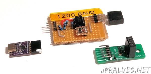
Pin PA6 is the hardwired DAC output, and it controls the IR LED power level. There’s no way to route the hardware TX internally to that pin, so I had to write some code to bit-bang UART-compatible bits out of it on demand. I set one of the timer peripherals to 1200 baud (see below), and had its Interrupt Service Routine set the DAC output to minimum or maximum, to send out a “0” or a “1”.
Protocol and Programmer
Since objects come and go in front of the module, I had to make sure that only legitimate communication will be treated as such. My very simple protocol has four-byte packets, transmitted at 1200 baud – slow enough for the rise and fall times of all the hardware involved (especially the phototransistor). The bytes themselves are a fixed preamble (0x5A), two data bytes (power and threshold settings), and a simple checksum byte to make sure the message was received correctly. The probability of random interference creating a seemingly-valid message is therefore infinitesimal.
By the way, on the electrical level, UART transmitters are idle-high, which is not guaranteed with the IR components. But that’s ok – as long as we provide a short “high” period before and after each byte, the receiver will understand.
As mentioned above, some hardware is required to translate the bytes coming to and from the PC to the IR medium. I designed a small PCB with a connector to a cheap USB-to-UART module, an OPB732, a transistor (to activate the LED per TX) and an OpAmp (to set the voltage on RX per the light falling on the phototransistor). Holding this setup stable directly in front of the sensor module, at a distance of ~25cm, yields good results – most of the messages arrive correctly, and the protocol filters out the few who don’t.
p.s., the ATtiny212 has to be programmed too, at some point. I put three SMD pads at the bottom of the module PCB for Vcc, GND and UPDI – the nice programming interface for modern AVRs. These can be accessed using a standard programmer (e.g. PICKIT 4) or a homebrew one, and a couple of pin headers, jumper wires or pogo pins.
Caveats
If I had to design a programmable sensor module from scratch, I’d probably have it communicate by half-duplex UART through its “signal out” pin. It’s extremely simple and cheap to implement, the communication is very reliable, and the sensor can be handled seamlessly by the main system, instead of a human operator standing nearby with a laptop and a programmer. But the main system has to be built with this kind of sensor “in mind”, which was not the case here.
Because the distance reading and the RX operate in parallel, my module can’t tell them apart in real time. Therefore, it will send rapid “object detected” signals to the main system whenever communication is attempted. This may or may not be a problem, depending on what the system does and expects at the time.
My way of controlling the IR LED current using a BJT is… arguable. The transistor’s gain is notoriously inaccurate and unstable over temperature, voltage, individual components etc. The only excuse I can offer (except for the low price) is that my design is good enough for the job it was meant to do. Your mileage may vary, of course.”