
“A Wheatstone bridge is an electrical circuit used to measure an unknown electrical resistance by balancing two legs of a bridge circuit, one leg of which includes the unknown component. The primary benefit of the circuit is its ability to provide extremely accurate measurements (in contrast with something like a simple voltage divider). Its operation is similar to the original potentiometer.
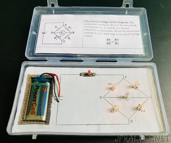
The Wheatstone bridge circuit mainly consists of two known resistors, one variable resistor, one unknown resistor (whose value to be calculated) and a Galvanometer (detect and measure small amounts of current in an electrical circuit). In the place of the resistors and galvanometer I have used small bulbs which I got from old decorative lighting strip. The resistance of all the bulbs are same. Alternatively, You can use torch light bulbs.
The Wheatstone bridge works on the principle of null deflection, i.e. the ratio of their resistances are equal and no current flows through the circuit. Under normal conditions, the bridge is in an unbalanced condition where current flows through the galvanometer. The bridge is said to be in a balanced condition when no current flows through the galvanometer. This condition can be achieved by adjusting the known resistance and variable resistance.
In the figure, Rx is the fixed, yet unknown, resistance to be measured. R1, R2, and R3 are resistors of known resistance and the resistance of R2 is adjustable. The resistance R2 is adjusted until the bridge is “balanced” and no current flows through the galvanometer Vg. At this point, the potential difference between the two midpoints (B and D) will be zero. Therefore the ratio of the two resistances in the known leg (R2 / R1) is equal to the ratio of the two resistances in the unknown leg (Rx / R3). If the bridge is unbalanced, the direction of the current indicates whether R2 is too high or too low.
Detecting zero current with a galvanometer can be done to extremely high precision. Therefore, if R1, R2, and R3 are known to high precision, then Rx can be measured to high precision. Very small changes in Rx disrupt the balance and are readily detected.
For more information visit this link: -https://en.wikipedia.org/wiki/Wheatstone_bridge
For the implementation of this principle, I used 4 bulbs in the place of resistors. Also add on 1 bulb in the place of Galvanometer.
Supplies:
- Cardboard
- A4 white paper Sheet
- Plastic box (size= 16cm X 8cm X3.5cm)
- Adhesive Glue
- Five Bulbs from Decorative light strip
- Female double row header connectors (total = 5)
- ON/OFF Switch
- One 9V battery
- Wires
- Thermocol Sheet
- Screws
Tools:
- Scissors
- Wire Stripping Plier
- Vernier Caliper Digital
- Soldering Iron
- Screwdriver
- Cardboard Cutter
- Adhesive tape
- Printer
- Multimeter”