
“The RP2040 based Pico can be used as a logic analyzer with PIO. The example be expanded to export the results to sigrock and PulseView.
Background
The new RP2040 process on the Raspberry Pi Pico comes with a Programmable IO (PIO) module. This module has many uses to directly control the GPIO of the board at high speed. An example that comes with the Pico shows how to use PIO to capture input on a pin as a logic analyzer. The included example prints out a simple ASCII display of the data and while interesting, it is hard to examine the ASCII printout in detail.
There is an open source project called sigrok that does signal analysis. (SIgnal GROK). Along with sigrok there is a companion project called PulseView that allows you to visually inspect the signal data. These two programs allow you to more easily analyze captured data, adding protocol decoders to see what the data you captured means.
This project aimed to expand the example logic analyzer program to produce data that can be displayed in PulseView and allow the analyzer to be interactively configured.
Overall Architecture
The idea behind the project so far is in 3 areas:
Connect the Pico to the pins on the device to be measured
Use modified example code to configure the logic analyzer settings and record the signals and output them to the serial device in a CSV format
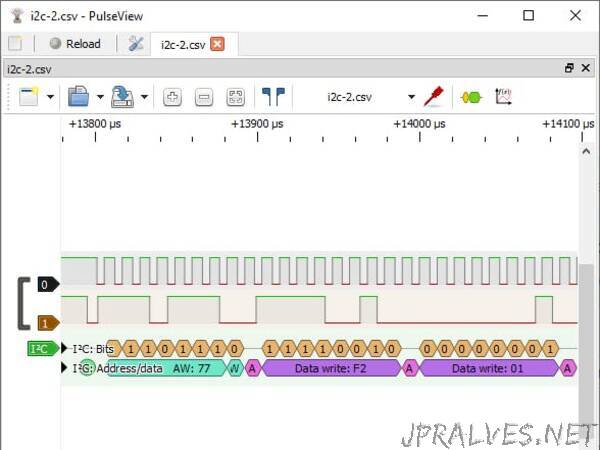
Use PulseView to import the CSV file and display the data
Note: sigrok has many hardware drivers built in to read a wide range of analyzers and scopes available. This project is not adding a new driver and just importing data via a CSV file.
The Code
The following assumes you know how to build a project and install it on a Pico. If you do not please see the excellent documentation that the has been released along with the Pico.
The example code that comes with the Pico was made to demonstrate a PIO program with a DMA transfer. To improve this for use as a logic analyzer several changes were made:
The program first is in an interactive mode allowing the user to configure settings such as number of pins to capture, number of sample rates, frequency, etc. After initializing the PIO will arm and wait for the trigger signal then capturing the data and writing it in CSV format to the serial output (via USB). This can found found in the function read_user_input().
A new print buffer function was created to write the data out in CSV format. This is found in print_capture_buf_csv().
The built in LED is set to be solid while armed and waiting, and blinking while transferring the data.
The functions logic_analyser_init() and logic_analyser_arm() are as is from the original example and are responsible to initialize the PIO program and arm it for the trigger value.
The attached GitHub repository has the code.”