
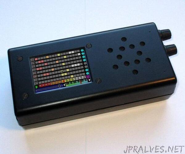
“A drum machine is a musical instrument which plays sequences and patterns. Usually drum machines produce percussion sounds, drum beats, etc. but this one has a built-in MIDI synthesiser, amplifier and speakers so it can produce “melodic” as well as percussive sounds. It allows you to program your own rhythms and beats.
You can also attach pads that allow you to play drum sounds “live”, either on top of a programmed drum beat or as a standalone performance.
The musical notes are produced by a MIDI chip - the VS1053 - which has 166 voices (i.e. allegedly-different instruments). It has a high degree of polyphony (up to 64) so it can play single notes or chords.
The patterns are programmed via a 320x240 touch screen. There are up to 8 tracks and up to a 16-step bar.
Each track can have a different “voice” and amplitude. There are 119 “melodic” voices and 47 “percussive” voices. With a melodic voice, such as a piano, each beat on the track can play a different note.
You can save and load different “Setups” and switch between them during a performance.
The whole MIDI Sequencer operates stand-alone with its own speaker and battery.
If you’re going to copy my build, you will need an Arduino Nano (1.50), a VS1053 module (4.50), a 3.2” ILI9341 SPI display (7.80) and a few resistors. You’ll also need a case, some powered speakers and perhaps a lithium cell and a PSU but the details will depend on how you decide to build it. I got all those extras from car-boot sales and charity shops. Plus you’ll need the usual electronic workshop paraphernalia.
I chose the VS1053 module shown in the picture. Search eBay, Alibaba or your favourite supplier for a VS1053 module that looks like that. It works well “out of the box” without modification.
There seem to be two other VS1053 modules available on Alibaba and eBay a red one and a blue one. The blue one is the one I used in my MIDI Theremin, it too works without modification. The red one is manufactured to be in non-MIDI mode by default. You can modify the hardware or software to put it into “live” MIDI mode. Read the discussions at the bottom of my Theremin project to see how other people have got it working. Once you’ve got it into MIDI mode it will respond to the same messages as the module I used here. I haven’t tested it.
The VS1053 is a fine chip but rather complicated. I’m only using the MIDI part of it. It’s possible to control the VS1053 over a serial interface but I’m using the SPI bus as it’s more convenient with an Arduino Nano. Any byte you send over the SPI bus is treated as a MIDI command.
You’ll find lists of MIDI commands on the web. The VS1053 responds to some but not all of them. The DrumSynth0.exe program shows the ones that I know work. It’s available on GitHub.
You can download the VS1053 data sheet from the web. It’s a huge document and is hard going. Section “8.9 Supported MIDI Formats” is almost all it says about MIDI. Section “10.10 Real-Time MIDI” talks about using GPIO0 and GPIO1 to enable MIDI but the board I using here doesn’t require any special enabling. You can also download a list of MIDI messages (not all of which are supported by the VS1053).
Wire the VS1053 module to an Arduino Nano as shown and upload the INO file to the Arduino. I used a solderless-breadboard.
The connector of the VS1053 module is a double-row pin header. I made a lead using a ribbon cable connector from a scrapped PC.
The drumsynth0.ino sketch receives a byte from the PC over the serial line and sends the byte to the VS1053. It’s a very simple program which allows you to test the VS1053. Connect the output jack socket to headphones or a computer speaker.
The Windows DrumSynth0.exe program (download ) sends commands to the VS1053. Click the “90 note vel” button to play a note. Or you could write your own Windows program. Or use one of the many terminal programs available on the web.
The VS1053 module has the following pins:
the SPI bus has the usual MISO, MOSI and SCLK
if XRST is low, the chip resets
XDCS doesn’t do anything in SPI mode so tie it to XCS
XCS is Chip Select
DREQ tells you when the chip is ready for a new command.
XCS should be set low while you’re sending a byte; then high. That way, you’re sure you have synchronised the first bit of each byte. Reading DREQ tells you that the chip is ready to receive a new command (I ignore it).
After the Arduino sends a byte, it must send a dummy byte so as to toggle the clock and allow the VS1053 to send a byte back in response. The SPItransfer() function shows you how.
Now you’re confident you can make the VS1053 work, we’ll turn it into more of a musical instrument. Attachments”