
“A 3-way OBD2 breakout board that allows you to monitor and route signals anywhere you want using simple jumper blocks and wires.
The OBD2 test board is designed to simplify OBD2 device development.
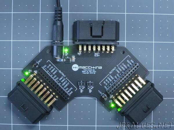
INPUT OBD2 Connector: 1 input OBD2 connector (MALE pins). This connector would plug into an OBD2 extension cable and eventually into a car’s OBD2 port.
OUTPUT OBD2 Connectors: 2 output connectors. (FEMALE pins). These connectors are the same as found in any modern car.
12V Input power source: Use in external 12V power adapter when doing desktop OBD2 development. If OBD2 extension cable is used, you’ll get power from the car and won’t need the external power source.
Power jumpers: Control power to each output by installing Jumpers. GREEN LED confirms power is ON.
Junction blocks: Route OBD2 signals to the connectors as needed. All signals are broken out and available. More about Junction block functionality below.
CAN termination resistors: 2 sets of termination resistors are available. These are typically used when using an emulator.
Junction blocks
The junction blocks near both OUTPUT OBD2 connector gives you the flexibility to change how signals move between connectors. Install a jumper wire between rows to make “through” connections, or jump over to other pins to rearrange signals.
Warning - be careful when rearranging signals between OBD2 connectors. Not all pins have same voltage levels.
The row closest to the OBD2 connector goes directly to the connector.
The row farthest from the OBD2 connector goes directly to the INPUT OBD2 connector.”