
“Hey guys, I am back with another cool Robot chassis from BangGood. Hope you have gone through our previous projects – Spinel Crux V1 – The Gesture Controlled Robot, Spinel Crux L2 – Arduino Pick and Place Robot with Robotic Arms and The Badland Brawler which we published last month. Looks cool with under glowing lights right?
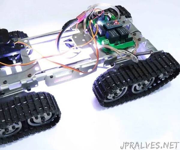
This time I have a rough Terrain Robot with 4 Wheel Drive and dedicated suspension for it to travel over rough terrain. Check it out. Why not build one for yourself? Here we will learn how to build a Off Road Wireless Multipurpose 4 Wheel Drive Arduino Tracked Robot for a smooth ride over rough terrain – A DIY Rough Terrain Wireless Crawler with Suspension.
We will provide you with the design, code, circuit diagrams and links to buy your own robot kit, chassis and the sensor modules used in this project.
Online PCB Manufacturer – JLCPCB
JLCPCB is one of the best Online PCB manufacturing company from where you can order PCBs online without any hassle. The company works 24 hours a day, 7 days a week nonstop. With their high tech machinery and automated work stream, they can manufacture huge quantities of high-class PCBs within hours.
JLCPCB can develop PCBs of various complexity. They develop Simple and cheap PCBs with Single layer board for hobbyists and enthusiasts as well as complex multi layer board for high standard industrial applications. JLC works with large product manufacturers and may be the PCB of devices you are using such as laptop or mobile phones were made at this factory.
HC12
HC 12 is a really cheap long range wireless module which can be used for wireless serial communication over a long distance of upto 1.7 KM. The module is really compact light weight and breadboard friendly which makes this the best wireless controller for our project.
Joystick
This is the most widely used robotic controller which comes with various robot DIY robot kit/robot arm kit that is built to work with arduino. The design is quite simple and is very easy to use. It uses two potentiometers to calculate the motion in the x axis and y axis and a switch to sense the button press. This can be easily connected to the arduino’s analog pins and read analog values directly.
Code for testing the joystick is available down below. Feel free to download/edit it as per your need. Download Before uploading the main code, make sure your joystick works by using this code.
Download the code from the above link.
In this example, what we are doing is simply collecting the data analog outputs from the Joystick using the analog pins (A0, A1,A2) of arduino. These values are stored in the variables and are later printed on the serial monitor
Arduino Pro Mini
This teeny tiny board was developed for applications and projects where space is premium and installations made permanent. Small, available in 3.3 V and 5 V versions, powered by ATmega328. Due to its small size, in this project we will be using this board to control Arduino Based Motor Driver Board.”